TPU Working Mode
In Sophon TPU, according to the difference of the main control unit (Host side), the TPU has two different working modes, which are called PCIe Mode and SOC Mode respectively.
PCIe Mode: The products in PCIe mode are SC series boards. The board is connected to the host server through PCIe interface. The host server act as the main control unit (Host) to control the operation of the board.
SoC Mode: The products in SoC mode are SE series devices. The inference device contains an 8-core A53 processor as the main control unit (Host) to control the operation of the board.
TPU Programming
TPU is a heterogeneous architecture, which requires the host to send instructions, and the device to receive the instructions and execute them. Therefore, to perform the calculation on TPU, it is necessary to write two parts of the code on host and device respectively:
Host: Host-side code, runs on the host and sends commands to control the TPU.
Device: Device-side code, running on the device, usually perform various instructions of the TPU.
To fit different target devices, the host-side and device-side codes need to be compiled with different compilers.
In PCIe Mode,
Host-side code compiler: The host’s C++ compiler used by user.
Device-side code compiler: Cross compiler runs by on-chip Linux ARM A53 processor (also called none ARM53 processor).
In SoC Mode, the code is compiled on x86 platform and runs on ARM A53 platform.
Host-side code compiler: Cross compiler runs by on-chip Linux ARM A53 processor.
Device-side code compiler: Cross compiler runs by on-chip Linux ARM A53 processor (also called none ARM53 processor).
The above ARM A53 cross compiler can be downloaded through the script scripts / prepare_toolchain.sh in the TPUKernel toolkit.
For device-side code, the compilation process can be seen as the process of updating dynamic link libraries.
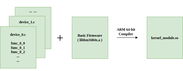
As shown in the above diagram, :cpp:func:device_*.c is the device-side code completed by the developer. The device-side code compiler links the device-side code with the original bottom library libbm1684x.a to form a complete A53Lite loadable raw dynamic library file.
Host Side
After completing the update of the above dynamic library, it is only necessary to load the dynamic library, and then send the call instruction from the host to control the TPU to run the specified calculation.
typedef struct _param_func{
...
...
}__attribute__((packed)) param_func_0_1;
bm_handle_t handle;
param_func_0_1 param;
bm_dev_request(&handle, 0);
tpu_kernel_launch_sync(handle, "func_0_1", ¶m, sizeof(param));
bm_dev_free(&handle);
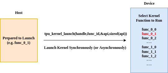
As shown in the figure above, the device firmware has already registered func_0_0() , func_0_1() , func_0_2() , func_1_0() , func_1_1() , func_1_2() … and other functions,
The host side now sends func_0_1(), and the TPU will perform the calculation of func_0_1().
There are two ways for the host to call the TPU for calculation, asynchronous and synchronous.
Synchronous Mode
Synchronous mode means that after sending the call command, the host will not continue to execute the following host-side code until the calculation on TPU is completed.
If the host calls the following API, it will wait for TPU until all calculation is completed.
- bm_status_t tpu_kernel_launch_sync(bm_handle_t handle, const char *func_name, const void *args, unsigned int size)
Launch the kernel function on device synchronously.
- Parameters
handle – Handle of the device.
func_name – Name of the kernel function to launch on device.
args – Pointer to the user-discript data package.
size – Size of the user-discript data package in bytes.
- Returns
Status of launching kernel function, BM_SUCCESS means succeeded, otherwise, some errors caught.
Asynchronous Mode
Asynchronous mode means that after sending the call command, the host will continue to execute the following host-side code. The TPU and the host run asynchronously.
If the host calls the following API, the TPU will start to calculate, and the host side will continue to execute the following code.
- bm_status_t tpu_kernel_launch_async(bm_handle_t handle, const char *func_name, const void *args, unsigned int size)
Launch the kernel function on device asynchronously.
- Parameters
handle – Handle of the device.
func_name – Name of the kernel function to launch on device.
args – Pointer to the user-discript data package.
size – Size of the user-discript data package in bytes.
- Returns
Status of launching kernel function, BM_SUCCESS means succeeded, otherwise, some errors caught.
The host can achieve synchronization with the TPU through the following API. After calling it, the host will wait for TPU to complete calculation.
- bm_status_t tpu_kernel_sync(bm_handle_t handle)
Synchronize the device.
- Parameters
handle – Handle of the device.
- Returns
Status of launching kernel function, BM_SUCCESS means succeeded, otherwise, some errors caught.
Device Side
In the previous section, we introduced how to drive the TPU to perform calculation. In this section, we will start to learn how to write device-side code and use TPU to complete the calculations we defined. Before that, we need to understand what basic instructions are defined by TPU. In the TPU Architecture section, we have introduced the entire calculation process of the TPU. This process can be divided into three parts:
Copy data between host memory and system memory back and forth.
Copy data between system memory and local memory back and forth.
The TPU perform calculations on the data in local memory.
The first part is related to the host-side. Since the data are saved in host memory, the related API is usually called by host. For the relevant commands on host side, please refer to the previous section.
Command System
· GDMA Command
Operations related to data transfer between system memory and local memory are all done by GDMA commands.
GDMA-related commands all start with tpu_gdma_() , including data transfer between different local memory and between different system memory.
For detailed command descriptions and parameters, please refer to the TPU API chapter.
· BDC Command
Operations related to data calculation performed by the TPU can be completed by BDC commands. All BDC commands start with tpu_bdc_().
· HAU Command
Some commands that are not suitable for parallel accelerated computing, including NMS, SORT, etc.
Memory and Data Alignment
· Data Representation
Tensor
In TPU, data is stored as a tensor. Tensor is a 4-dimensional array. We use a 4-tuple (N,C,H,W) to describe the shape of a tensor. Tensor(n, c, h, w) represents the data element at index of (n, c, h, w).
A tensor in local memory can not be described only by the address, shape and data type, the strides are also necessary. For a 4D tensor with shape (N, C, H, W), there are four relative strides named N_stride, C_stride, H_stride and W_stride.
Stride indicates how many elements are separated between elements of the same dimension when tensor is stored in local memory.
For arbitary n in [0, N - 1], c in [0, C - 1], h in [0, H - 1] and w in [0, W - 1],
N_stride: number of elements from (n, c, h, w) to (n + 1, c, h, w).
C_stride: number of elements from (n, c, h, w) to (n, c + X, h, w), where X is the number of NPUs.
H_stride: number of elements from (n, c, h, w) to (n, c, h + 1, w).
W_stride: number of elements from (n, c, h, w) to (n, c, h, w + 1).
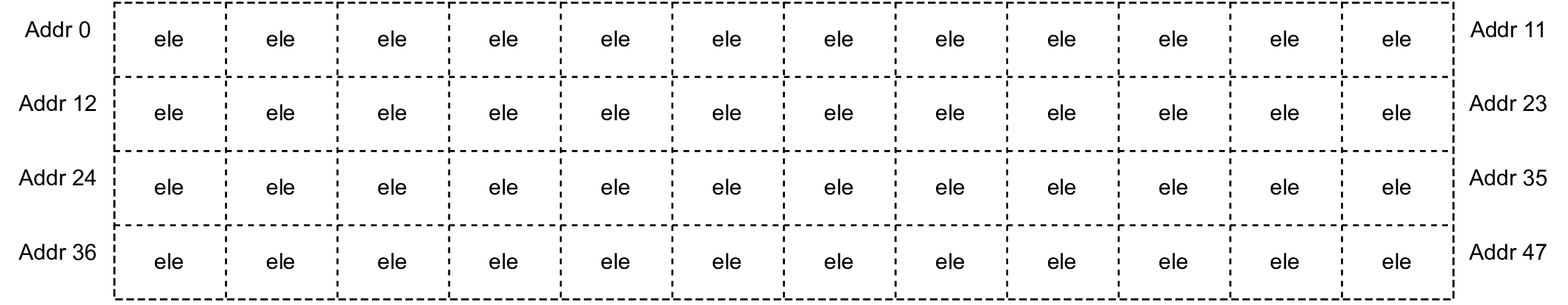
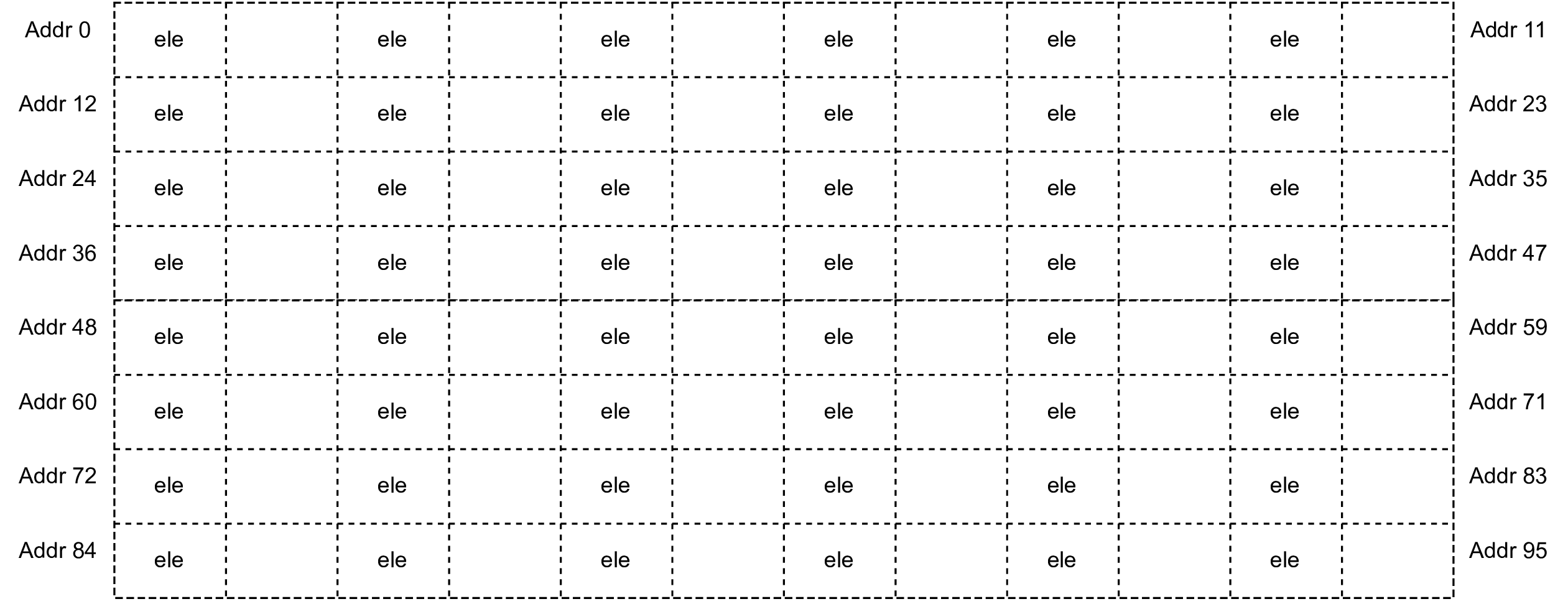
Suppose there is a tensor has a shape of (4, 3, 2, 2), each of its elements occupies 1 byte. If its stride in local memory is (12, 4, 2, 1), it will be arranged as shown in the following figure:
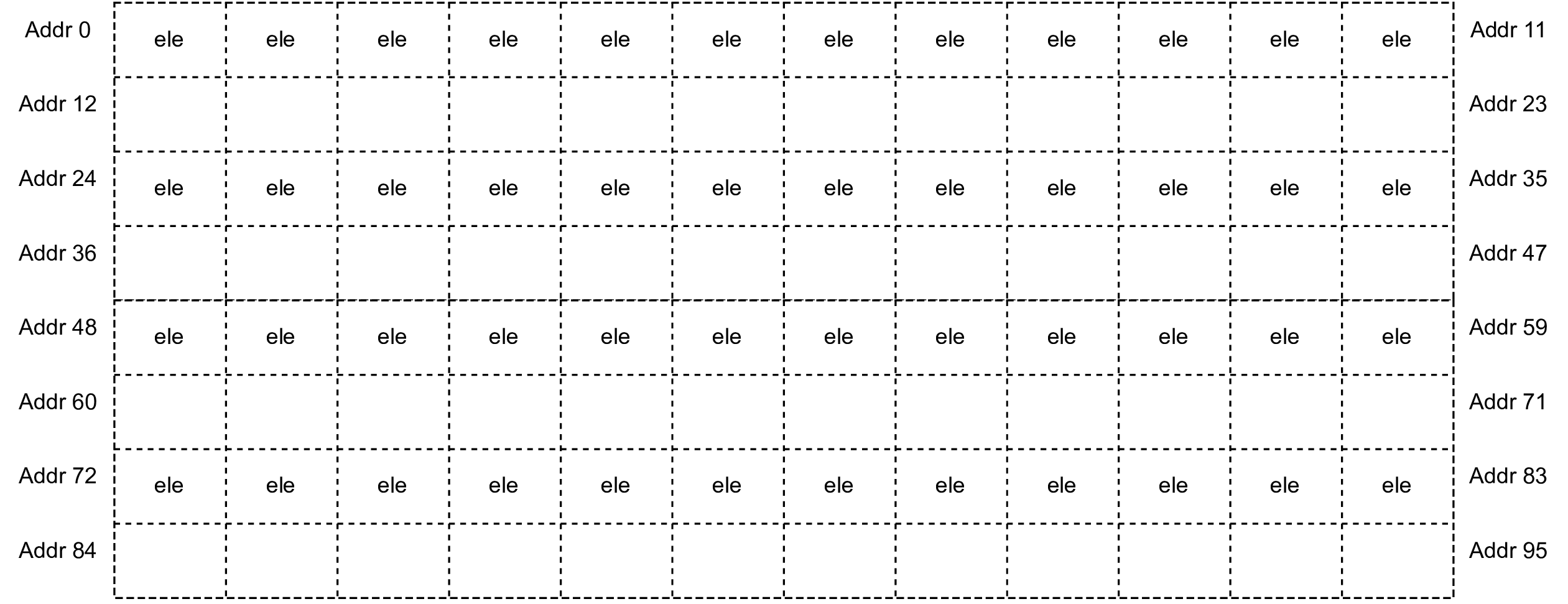
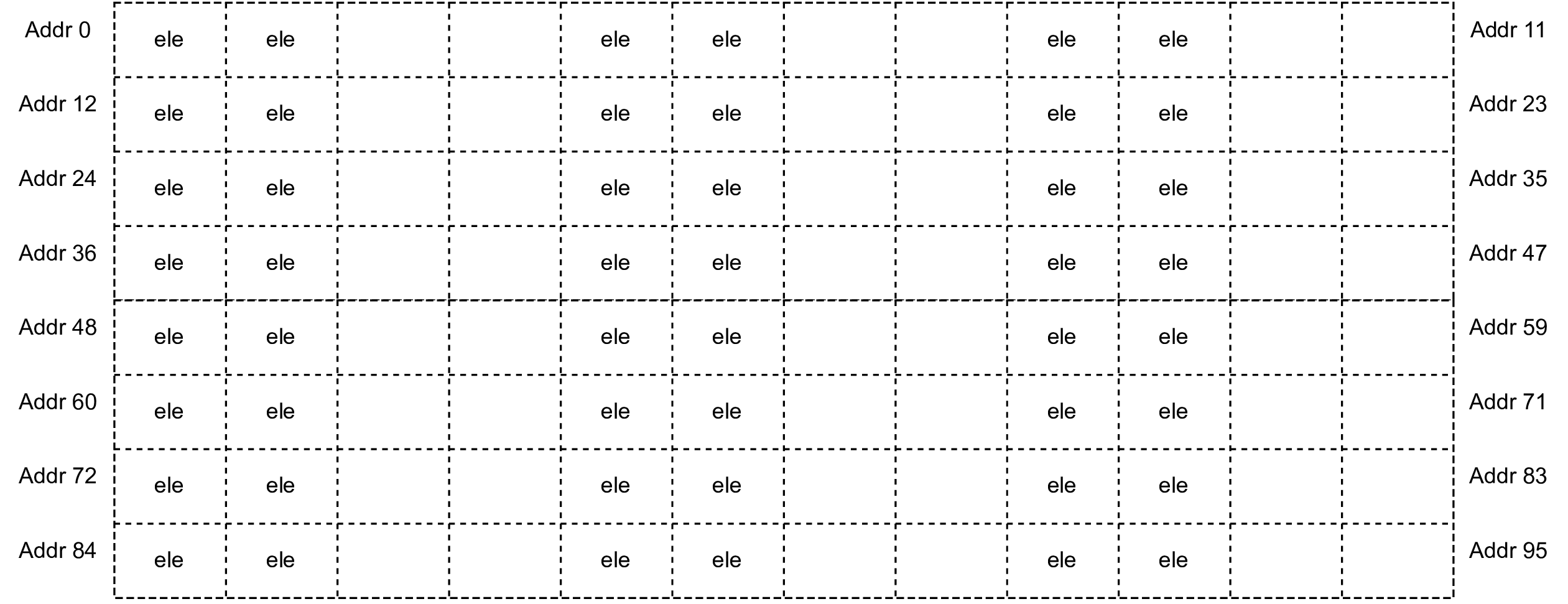
If the stride is (24, 4, 2, 1), it will be arranged as follows:
If the stride is (24, 8, 4, 2), it will be arranged as follows:
If the stride is (24, 8, 4, 1), it will be arranged as follows:
Data Type
The unit of Stride is the number of elements. Different types of data elements have different bytes. The data types in following are supported on BM1684x TPU:
· Tensor Layout in Global Memory
Global memory consists of a piece of DDR memory.
A tensor with shape of (N, C, H, W), arranged in global memory. If its stride is:
W_Stride = 1,
H_Stride = W,
C_Stride = H*W,
N_Stride = C*H*W.
This layout is called continuous storage.
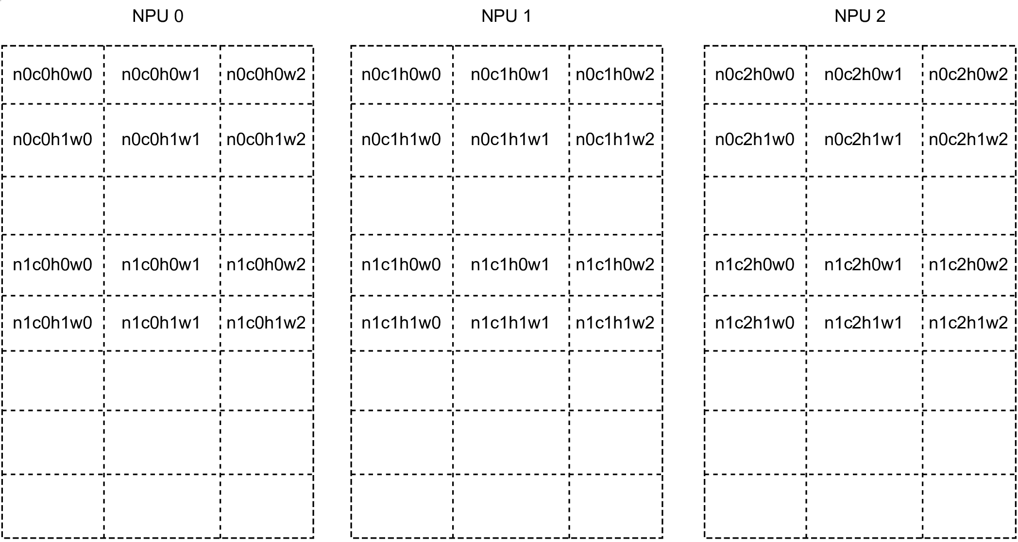
Example: A tensor with shape of (N=2, C=2, H=3, W=2) is arranged in global memory as follows:
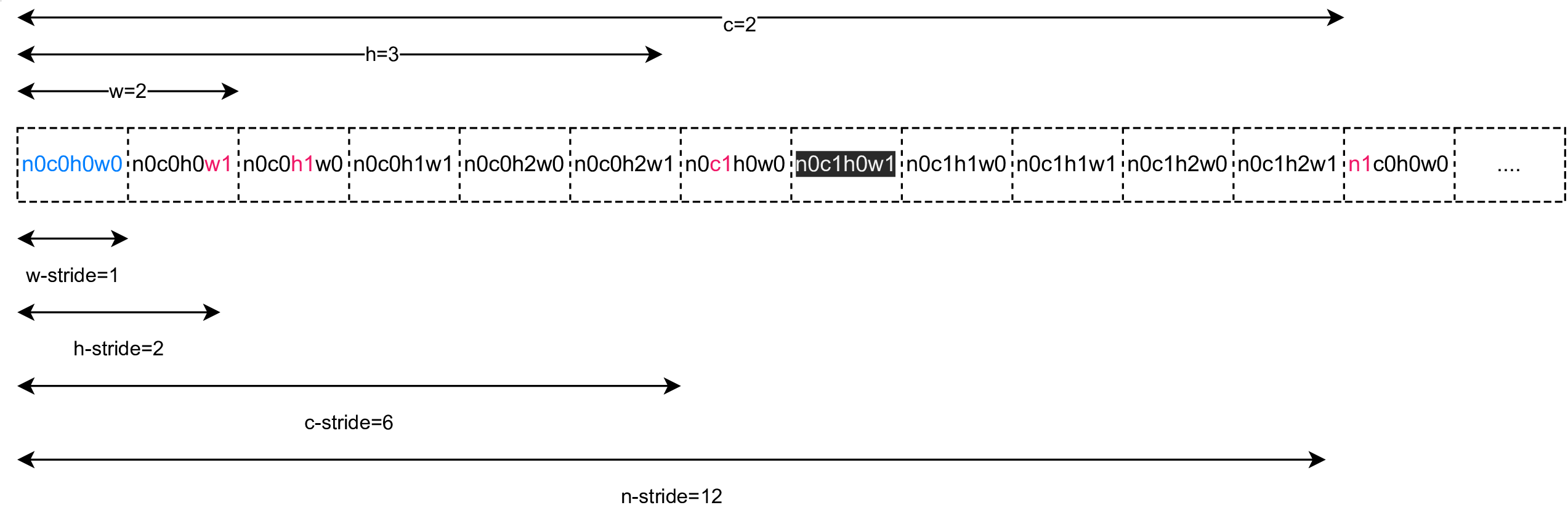
In the figure above, n0c0h0w0 represents the element at the position of Tensor(0,0,0,0).
· Tensor Layout in Local Memory
Composition and Address of Local Memory
The local memory consists of multiple pieces of SRAM (Static Random Access Memory), and each piece of SRAM is called a bank. The BM1684x consists of 16 banks in total. 16 banks constitute the whole local memory.
The entire local memory is also divided into 64 lanes (corresponding to 64 NPUs, and then NPUs are used to refer to lanes). The address assignment is shown in the following figure:
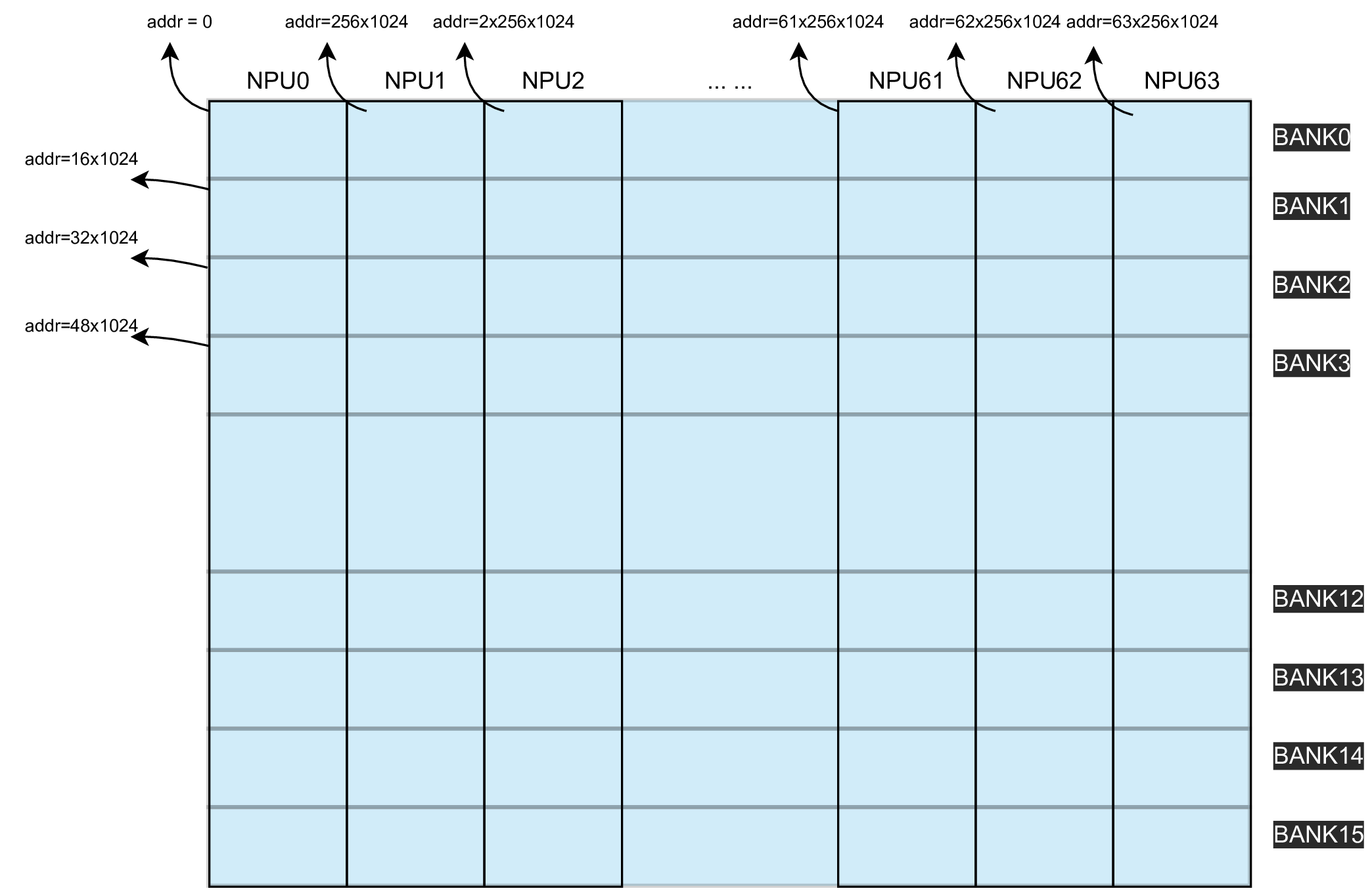
The local memory size of BM1684x is 256KB * 64, and the address is allocated according to the NPU. Among them, NPU0 has the address of 0~256*1024-1, NPU1 has the address of 256*1024~2*256*1024-1, and so on.
Rules for Tensor Layout in Local Memory
The layout of tensors on local memory is different from global memory. The main difference is the layout in the C dimension.
For a tensor with shape (N, C, H, W), it has N * C features, if copied to local memory, the features will be scattered to different NPUs. Denote the feature (n, c, :, :) simply by (n, c), where n is in [0, N - 1] and c is in [0, C - 1]. Let the number of NPUs be X.
Example: A tensor with shape(N=2,C=3,H=2,W=3),stride(N_stride = 9, C_stride = 9, H_stride = 3, W_stride = 1). The layout on local memory is as follows.
Another important concept is the number of channels per NPU. Supposing the tensor starts at NPU Q, the number of channels per NPU is ceil((Q + C) / X). The \(ceil\) function represents rounding up to an integer.
Case 1: Supposing C = X - 1 and the tensor starts at NPU 0, the following figure shows how the features are scattered (Note that each block represents a memory area for storing a feature).
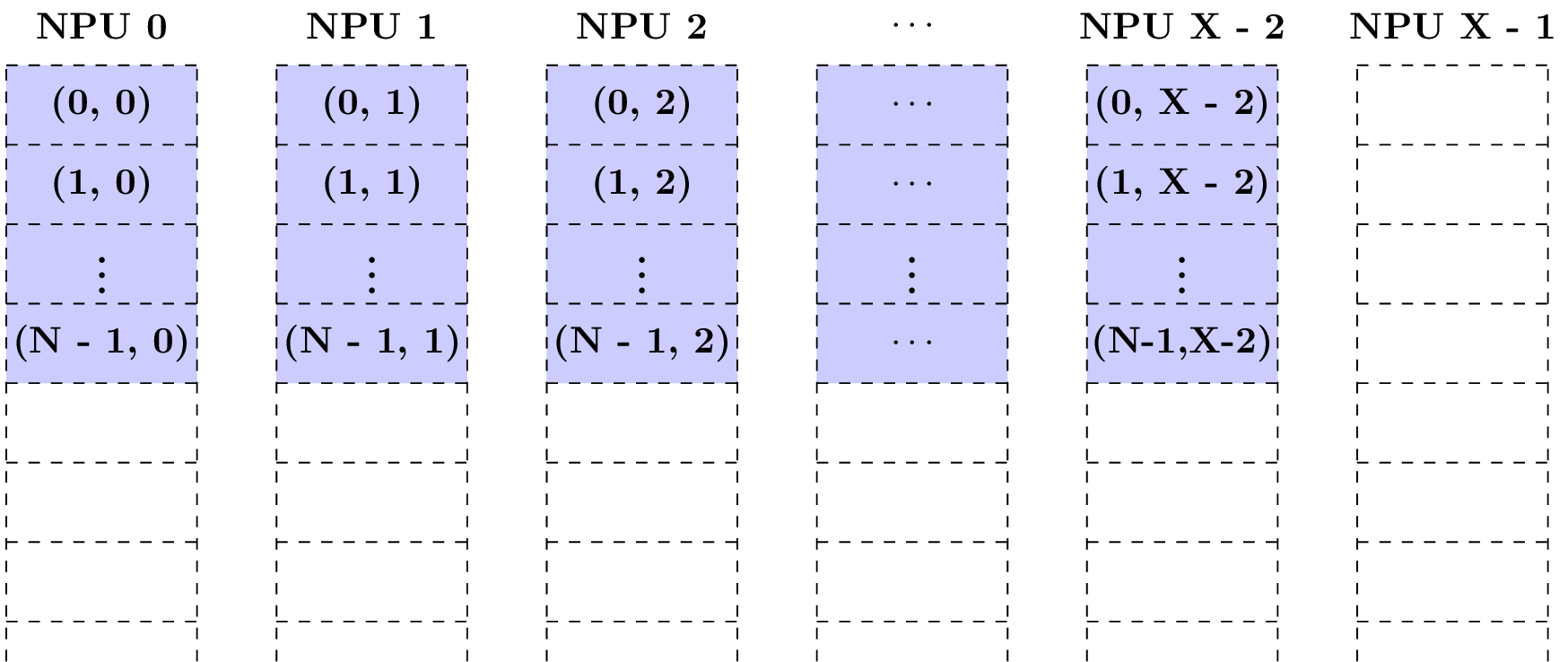
No features are scattered to NPU X - 1, the feature (1, 0) is not in NPU X - 1, instead, it is in NPU 0. It is found that the features (*, c) are in the same NPU for arbitary fixed c in [0,C - 1]. The number of channels per NPU is ceil((0 + X - 1) / X) = 1.
Case 2: Supposing C = X - 1 and the tensor starts at NPU 1, the following figure shows how the features are scattered.
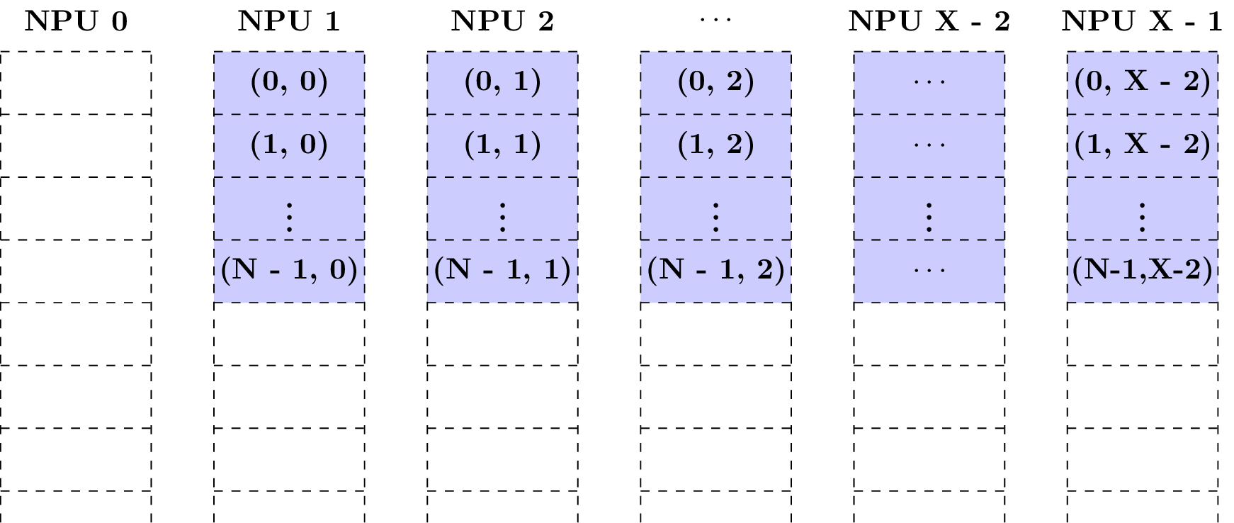
No features are scattered to NPU 0, like NPU X - 1 in the previous case. Still, the number of channels per NPU is ceil((1 + X - 1) / X) = 1.
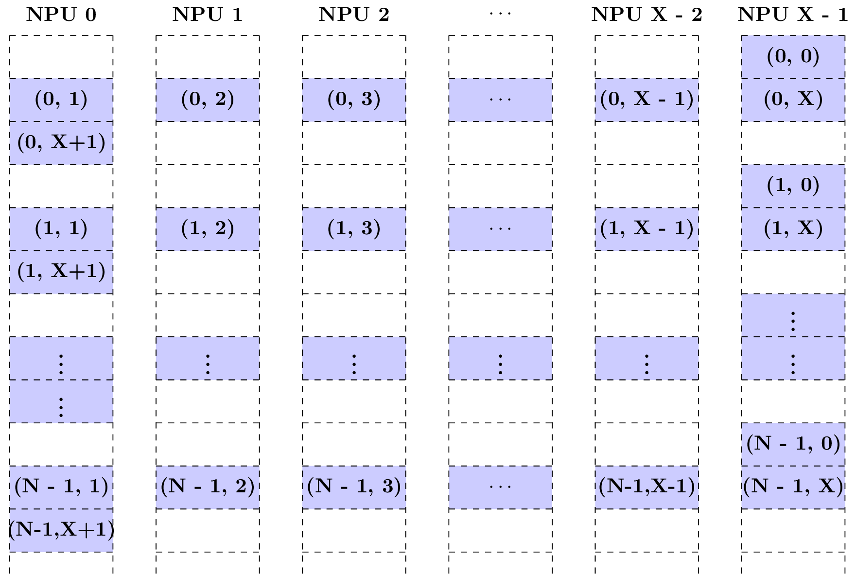
Case 3: Supposing C = X + 2 and the tensor starts at NPU 0, the following figure shows how the features are scattered.
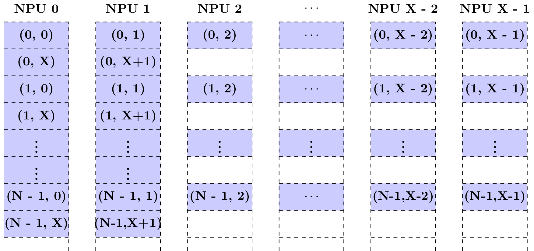
The features (*, X) and (*, X + 1) are scattered to NPU 0 and NPU 1, respectively. In the second block row, there are X - 2 empty blocks storing nothing about this tensor. The number of channels per NPU is ceil((0 + X + 2) / X) = 2.
In this case, not only the features (*, c) are in the same NPU, but also (*, c + X) if c + X is in [0, C - 1]. The features (*, c_0) and (*, c_1) are in the same NPU if and only if c_0 mod X = c_1 mod X.
Case 4: Supposing C = X + 2 and the tensor starts at NPU X - 1, the following figure shows how the features are scattered.
Three block rows are used to store the C features of one batch with X - 1 empty blocks in each the first and third row. The number of channels per NPU is ceil((X - 1 + X + 2) / X) = 3. Such a storage is terrible and causes a lot of waste of local memory.
If reusing the empty blocks to store some other tensors, it should be much careful and know the TPU well, otherwise, the data in these tensors may be destroyed when NPUs work in parallel. Try not to reuse the empty blocks.
Common Layout in Local Memory
The previous chapter describes the basic principles of layout in local memory. Next, we introduce several tensor layouts commonly used in BM1684x.
1. 64-Byte Aligned Layout
64-byte aligned layout is most commonly used. If a tensor with shape (N, C, H, W) is in the aligned layout, it is required that
The address of the tensor is divisable by 64.
The W_stride is 1.
The H_stride is W.
The C_stride is ceil(H * W / 16) * 16 if the data type is 32-bit, ceil(H * W / 32) * 32 if the data type is 16-bit, ceil(H * W / 64) * 64 if the data type is 8-bit.
The N_stride is the C_stride multiply by the number of channels per NPU.
The strides can be obtained by calling tpu_aligned_stride().
To illustrate simply, the number of the NPUs is set to 4.
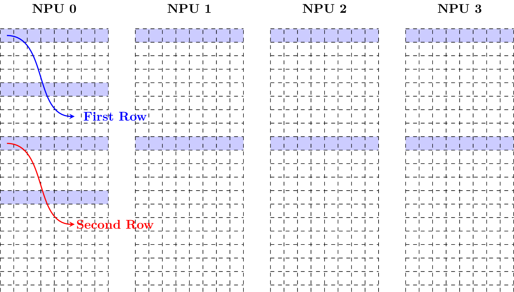
Given a tensor with shape (N = 2, C = 3, H = 4, W = 5) and data type fp16, the following figure shows how it is in the aligned layout (Note that each block has size of 2 bytes).
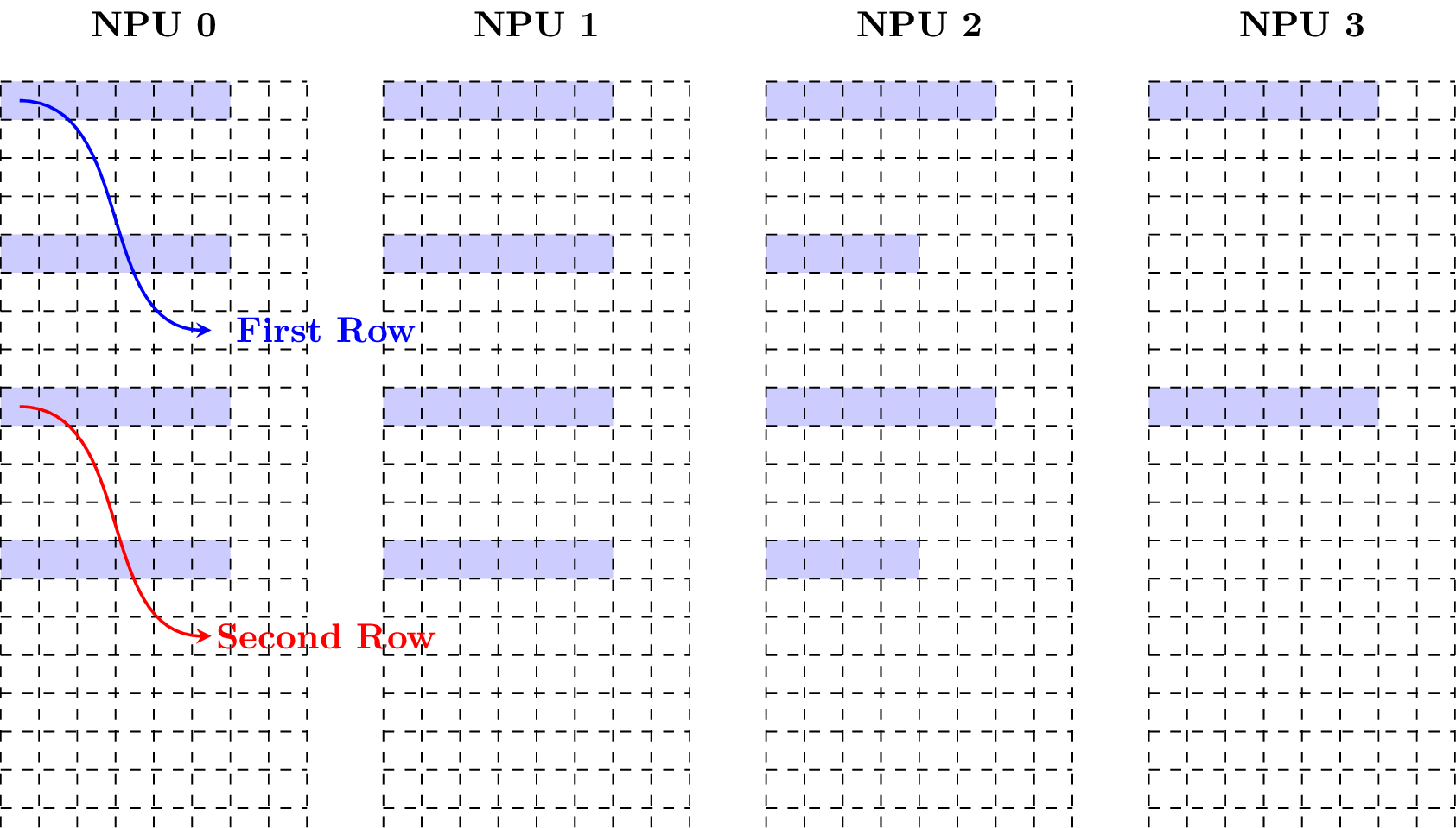
Supposing the tensor starts at NPU 2, the following figure shows how the tensor is in the aligned layout.
2. Compact Layout
Compact layout is also a commonly used layout. If a tensor with shape (N, C, H, W) is in the compact layout, it is required that
The address of the tensor is divisable by 4.
The W_stride is 1.
The H_stride is W.
The C_stride is H * W.
The N_stride is the C_stride multiply by the number of channels per NPU.
The strides can be obtained by calling tpu_compact_stride().
To illustrate simply, the number of the NPUs is set to 4.
Given a tensor with shape (N = 2, C = 3, H = 4, W = 5) and data type fp16, the following figure shows how it is in the compact layout (Note that each block has size of 2 bytes).
Supposing the tensor starts at NPU 2, the following figure shows how the tensor is in the aligned layout.
3. Matrix Layout
Matrix layout is a layout of matrix in local memory. If a matrix with size n-by-m is in the matrix layout, it could be viewed as a 4D tensor with shape (N = n, C = ceil(m / w), H = 1, W = w) in the 64-Byte Aligned Layout, where w is in [1, m] and given by user.
To illustrate simply, the number of the NPUs is set to 4.
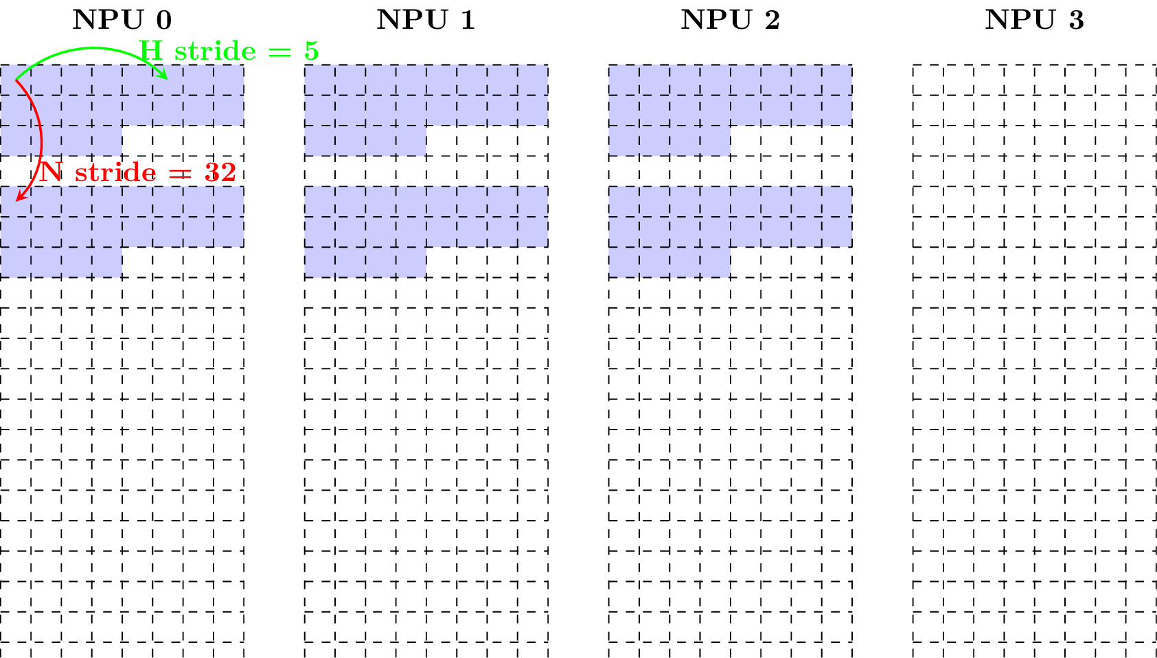
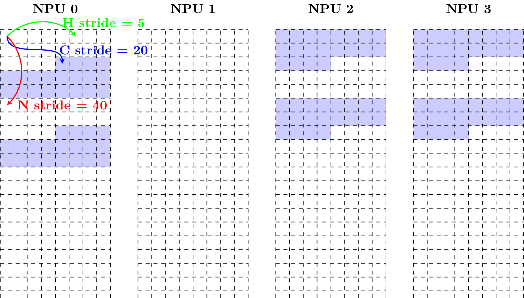
Example 1: Given a matrix with size 2-by-40 and data type fp16, w = 40, the following figure shows how it is in the matrix layout (Note that each block has size of 2 bytes).
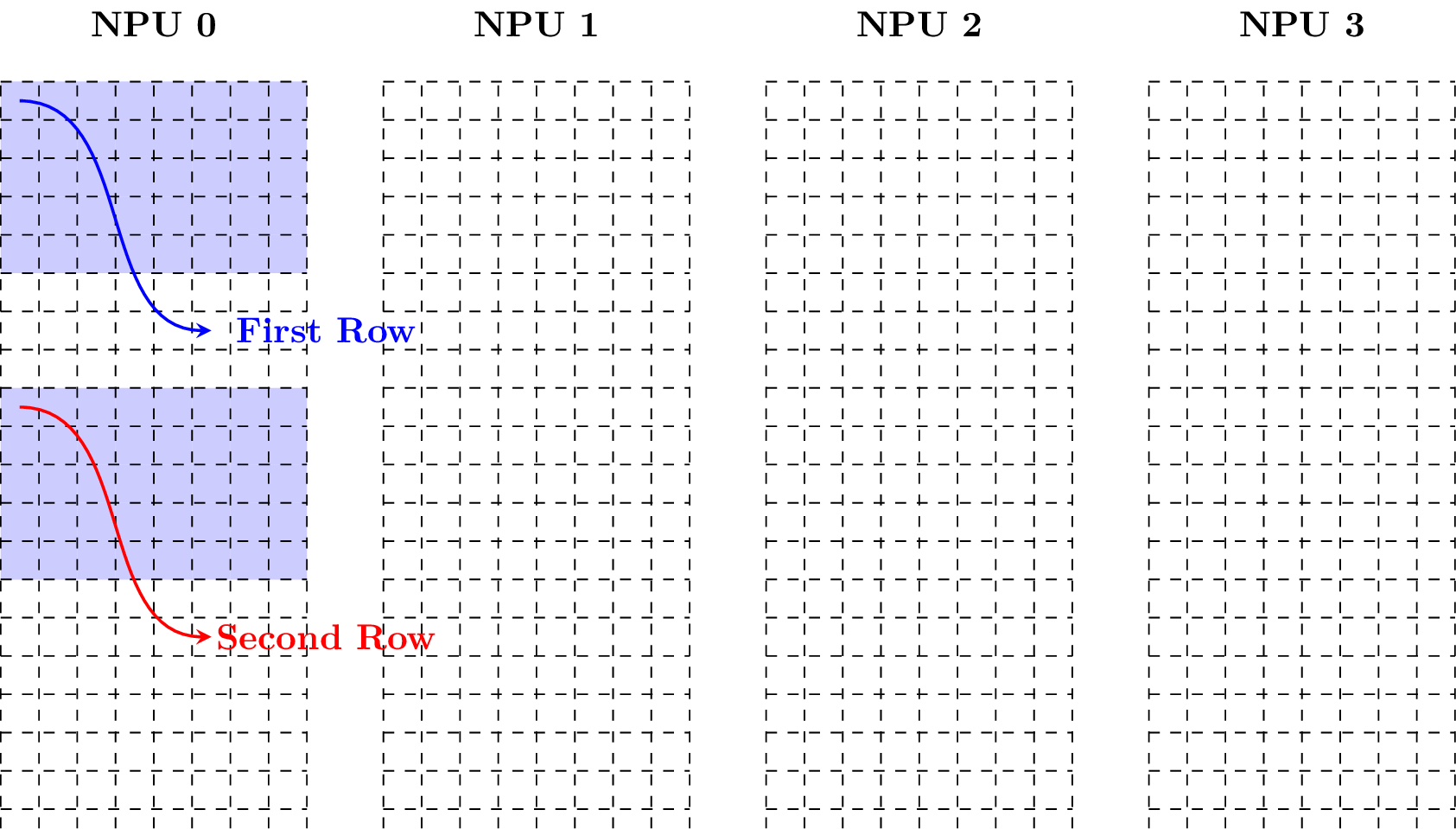
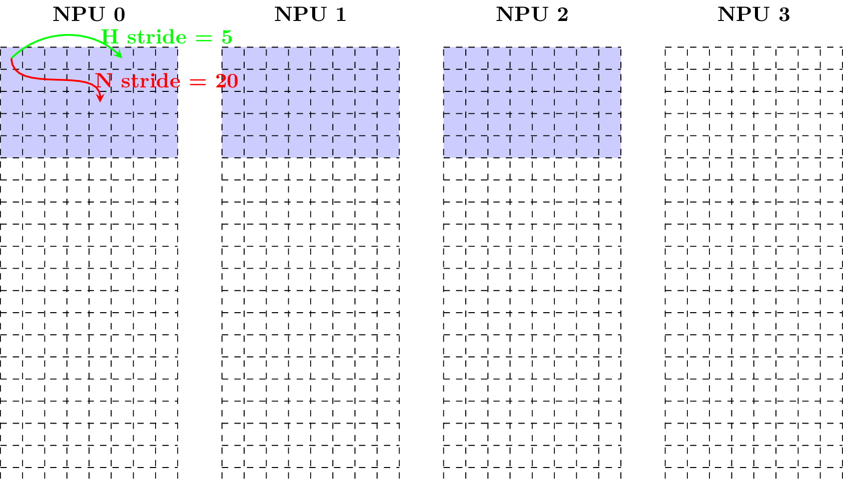
Example 2: Taking w = 20, the following figure shows how the matrix is in the matrix layout.
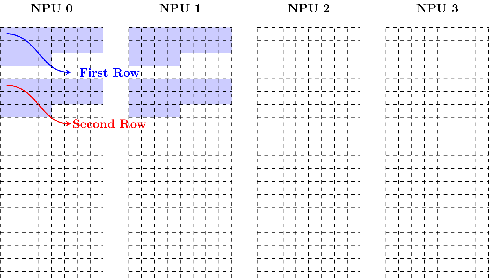
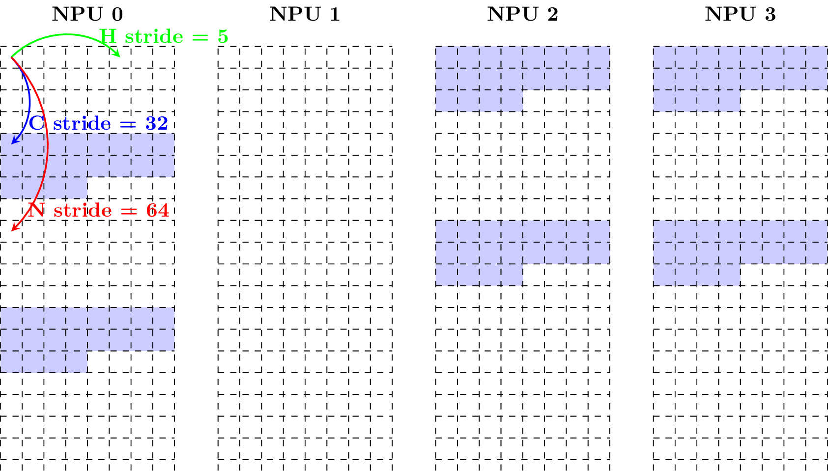
Example 3: Taking w = 15, the following figure shows how the matrix is in the matrix layout.
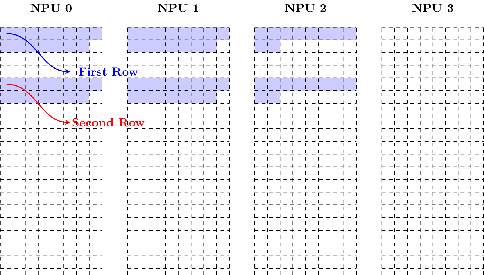
Example 4: Keeping decreasing w and taking w = 8, the following figure shows how the matrix is in the matrix layout.
Example 5: Taking w = 6, the following figure shows how the matrix is in the matrix layout.
4. Vector Layout
Vector layout is a layout of vector in local memory. If a vector with size 1-by-m is in the vector layout, it could be viewed as a 4D tensor with shape (N = 1, C = ceil(m / w), H = 1, W = w) in the 64-Byte Aligned Layout, where w is in [1, m] and given by user.
5. Line 64-Byte Aligned Layout
Line 64-byte aligned layout is a layout of tensor in local memory. If a tensor with shape (N, C, H, W) is in this layout, it is required that
The address of the tensor is divisable by 64.
The W_stride is 1.
The H_stride is ceil(W / 16) * 16 if the data type is 32-bit, ceil(W / 32) * 32 if the data type is 16-bit, ceil(W / 64) * 64 if the data type is 8-bit.
The C_stride is H * H_stride.
The N_stride is the C_stride multiply by the number of channels per NPU.
The strides can be obtained by calling tpu_line_aligned_stride().
6. 64IC/32IC Layout
64IC/32IC layout is a special layout of the convolution kernel in local memory. It is only used for the convolution. The kernel is stored in 64IC layout with the data type of INT8, and stored in 32IC layout with the data type of FP16 or BFP16.
Suppose the shape of the convolution kernel is (ic, oc, kh, kw), which represent the input channel, the output channel, the height of the kernel, and the width of the kernel, respectively.
If the kernel is in 64IC layout, it is required that
W_stride = 64
H_stride = 64 * kw
C_stride = 64 * kw * kh * ceil(ic/64)
N_stride = 64 * kw * kh * ceil(ic/64)
Among them, each 64 channels are stored as a group, the stride of each group is 64 * kw * kh.
If the kernel is in 32IC layout, it is required that
W_stride = 32
H_stride = 32 * kw
C_stride = 32 * kw * kh * ceil(ic/32)
N_stride = 32 * kw * kh * ceil(ic/32)
Among them, each 32 channels are stored as a group, the stride of each group is 32 * kw * kh.