5. VQE Algorithm Function Introduction
5.1. Voice Quality Enhancement (VQE)
For speech signal processing (SSP) algorithms, when the near-end speech signal is interfered with by echo from the far end or stationary noise from the near end, the algorithm functions within SSP can be used to suppress these interferences and improve the quality of the speech signal. The solutions provided in SSP include linear echo cancellation (AEC), nonlinear echo suppression (AES), speech noise reduction (NR), automatic gain control (AGC), and other functions. The SSP algorithm supports speech signals with a sampling rate of 8kHz or 16kHz, mono channel, and 16-bit sampling length. The following pages will introduce each algorithm function and the parameters used.
The parameter “para_fun_config” corresponds to the “u32OpenMask” in the “cvi_comm_aio.h” file, which controls the SSP algorithm functions in the microphone path. The parameter “para_spk_fun_config” controls the SSP algorithm functions in the speaker path. The algorithm functions corresponding to each bit are described in the table below.
para_fun_config |
Description (Microphone Path) |
|---|---|
Bit 0 |
0: Turn off AEC 1: Turn on AEC |
Bit 1 |
0: Turn off AES 1: Turn on AES |
Bit 2 |
0: Turn off NR 1: Turn on NR |
Bit 3 |
0: Turn off AGC 1: Turn on AGC |
Bit 4 |
0: Turn off Notch Filter 1: Turn on Notch Filter |
Bit 5 |
0: Turn off DC Filter 1: Turn on DC Filter |
Bit 6 |
0: Turn off DG 1: Turn on DG |
Bit 7 |
0: Turn off Delay 1: Turn on Delay |
para_spk_fun_config |
Description (Speaker Path) |
|---|---|
Bit 0 |
0: Turn off AGC 1: Turn on AGC |
Bit 1 |
0: Turn off EQ 1: Turn on EQ |
5.2. AEC/AES (Acoustic Echo Cancellation/Acoustic Echo Suppression)
Any architecture of a duplex communication system has the interference of echo. An echo canceller can eliminate the echo caused by the speaker output coupled back to the microphone through the near-end acoustic path. By using the provided solution, the linear adaptive filter module (AEC) combined with the nonlinear echo suppression module (AES) can effectively suppress the echo and thus improve the quality of speech communication.
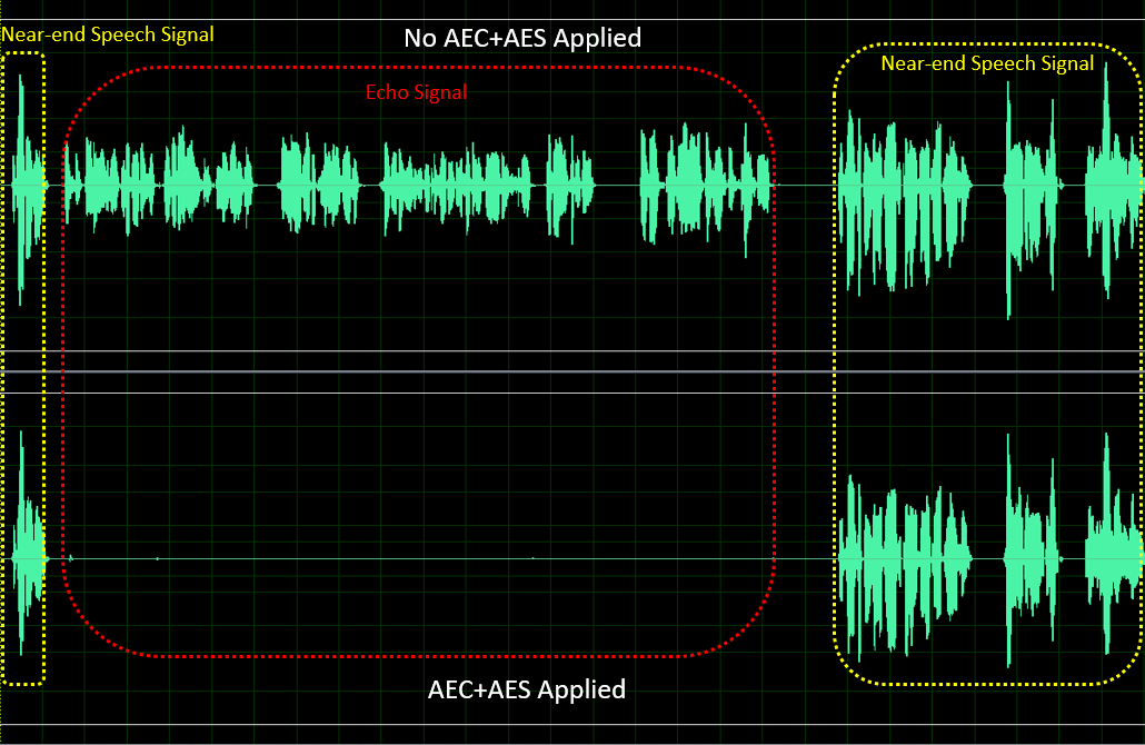
Figure: Performance before and after AEC+AES processing
Four adjustable parameters are provided to tune the performance of AEC/AES, namely:
para_aec_init_filter_len/para_aec_filter_len: the length of the adaptive filter. Adjust the appropriate filter length according to the different echo tail times of the samples. Selecting a longer length will result in higher MIPS and power consumption.
para_aec_init_filter_len is only used for tuning when the echo first appears.
para_aes_std_thrd: the threshold for residual echo detection. Setting a higher value will result in better quality of near-end speech but more residual echo. Conversely, setting a lower value will result in poorer quality of near-end speech but less residual echo.
para_aes_supp_coeff: the strength of residual echo suppression. Setting a larger value will result in stronger suppression of residual echo, but will also lead to more loss/damage of fine details in near-end speech.
AEC/AES Parameter |
Ad justable Range |
Description |
|---|---|---|
para_aec_init_filter_len/para_aec_filter_len |
1 - 13 |
8kHz sampling rate: [1,13] corresponding to [20ms,260ms] 16kHz sampling rate: [1,13] corresponding to [10ms,130ms] |
para_aes_std_thrd |
0 - 39 |
0: the threshold for residual echo detection is the smallest. 39: the threshold for residual echo detection is the biggest. |
para_aes_supp_coeff |
0 - 100 |
0: the strength of residual echo suppression is the smallest. 100: the strength of residual echo suppression is the biggest. |
5.3. NR (Noise Reduction)
The NR module can suppress stationary noise in the surrounding environment, such as fan noise, air conditioning noise, engine noise, white/pink noise, and so on. With the help of its proprietary speech intelligent “Speech VAD” algorithm, NR can preserve the speech signal while effectively suppressing stationary noise, thereby improving the quality of voice communication.
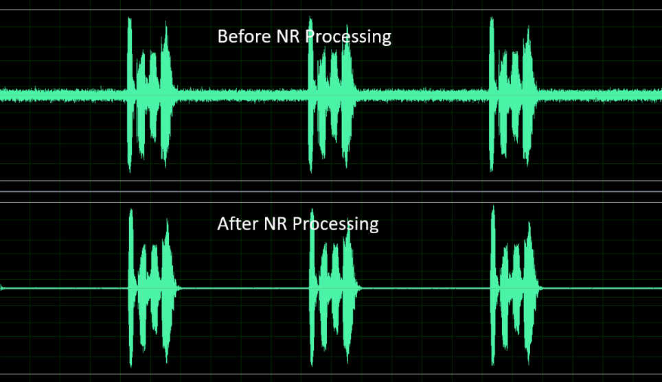
Fig. 5.1 Performance before and after NR processing
There are three adjustable parameters provided for tuning the performance of NR, which are:
para_nr_init_sile_time: the initial length of silence time. When the CODEC is powered on, it will produce random meaningless noise signals, and para_nr_init_sile_time can be set to silence this period of signal.
para_nr_snr_coeff: the signal-to-noise ratio (SNR) tracking coefficient. If the parameter value is large, NR will have higher noise reduction ability, but the speech signal may be more prone to distortion. Conversely, if the parameter value is small, NR will suppress less noise signals but will have better speech quality performance. The following table shows the appropriate adjustment range of this parameter based on different SNR environments. The larger the parameter value is for each SNR condition, the greater the suppression of stationary noise.
NR Parameter |
Adjustable Range |
Description |
|---|---|---|
para_nr_init_sile_time |
0 - 250 |
Corresponding to 0s to 5s, each stage is 20ms. |
The ambientenvironment ofSNR |
Adjustable Range |
Description |
|---|---|---|
Low |
0 - 3 |
0: It is the least active in noise reduction 3: It is the most active in noise reduction |
Medium |
4 - 10 |
4: It is the least active in noise reduction 10: It is the most active in noise reduction |
High |
11 - 25 |
11: It is the least active in noise reduction 25: It is the most active in noise reduction |
5.4. AGC (Automatic Gain Control)
The AGC module can automatically adjust the output level to a predetermined range, providing a more comfortable listening experience. If the input signal is below the “Target Low,” the AGC will adjust the output level towards “Target Low.” On the other hand, if the input signal is above “Target High,” the AGC will adjust the output level towards “Target High.”
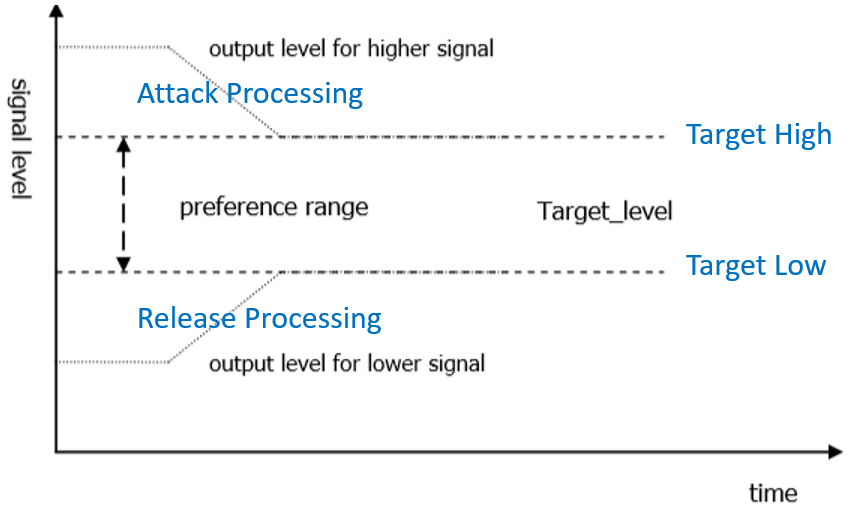
Fig. 5.2 AGC adjust the signal level
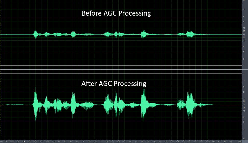
Fig. 5.3 Performance before and after AGC processing
Four adjustable parameters are provided to adjust the performance of AGC in the microphone path, which are:
para_agc_max_gain: This parameter is the maximum gain that the signal can be amplified.
para_agc_target_high: This parameter is the “Target High” level that the AGC will converge to. For input signals above para_agc_target_high, the AGC will converge to para_agc_target_high.
para_agc_target_low: This parameter is the “Target Low” level that the AGC will converge to. For input signals below para_agc_target_low, the AGC will converge to para_agc_target_low. If para_agc_max_gain is reached before para_agc_target_low, the AGC will only converge to para_agc_max_gain.
para_agc_vad_ena: Speech-activated AGC function. Enabling this function, while also enabling NR and AEC/AES functions, allows the AGC to avoid amplifying residual stationary noise and residual echo to achieve optimal results.
AGC Parameter |
Adjustable Range |
Description |
|---|---|---|
para_agc_max_gain |
0 - 6 |
The maximum increase gain corresponding to [0, 6] is [6dB, 42dB], with 6dB per step. |
para_agc_target_high |
0 - 36 |
0 to 36 corresponding to 0dB to -36dB |
para_agc_target_low |
0 - 72 |
0 to 72 corresponding to 0dB to -72dB |
para_agc_vad_ena |
0 - 1 |
0: Turn off Speech-activated AGC function 1: Turn on Speech-activated AGC function |
The three parameters para_spk_agc_max_gain, para_spk_agc_target_high, and para_spk_agc_target_low are used to adjust the performance of the AGC in the speaker path, and their parameter definitions and adjustment ranges are the same as those of the AGC in the microphone path.
5.5. Notch Filter
Notch FilterParameter |
Adjustable Range |
Description |
|---|---|---|
para_notch_freq |
0 - 1 |
0: notch frequency is 1kHz 1: notch frequency is 4kHz |
5.6. DG (Digital Gain)
This feature helps to reduce residual echo and residual stationary noise. It is not recommended to enable this feature if the gain level of the mic channel is small.
DG Parameter |
Adjustable Range |
Description |
|---|---|---|
para_dg_target |
1 - 12 |
1: The residual echo/noise suppression is the least aggressive, but provides the best voice quality. 12: The residual echo/noise suppression is the most aggressive, but provides the worst voice quality. |
5.7. Delay
This function is used to delay the reference signal and can accelerate the convergence of the echo that appears at the beginning of AEC/AES. If the convergence of the initial echo has already been accelerated by adjusting the parameter para_aec_init_filter_len, it is not recommended to enable this function.
Delay Parameter |
Adjustable Range |
Description |
|---|---|---|
para_delay_sample |
1 - 3000 |
1 to 3000 corresponding to 1 to 3000 samples |
5.8. Equalizer
This function is used for equalizing the speech signal, which can be adjusted by center frequency, gain, and quality factor of the band to achieve the desired frequency response of the speech signal, or to compensate for the imperfect frequency response caused by hardware or speaker units.
Equalizer Parameter |
Adjustable Range |
Description |
|---|---|---|
para_spk_eq_nband |
1 - 5 |
1 to 5 corresponding to 1 to 5 bands |
para_spk_eq_freq[] |
8kHz Fs: 0 - 9 16kHz Fs: 0 - 10 |
Band’s center frequency,refer to label para_spk_eq_freq |
para_spk_eq_gain[] |
0 - 60 |
Band’s gain,refer to label para_spk_eq_gain |
para_spk_eq_qfactor[] |
0 - 17 |
Band’s quality factor. 0: The frequency response curve centered at para_spk_eq_freq is smoothest, but has the widest range of influence on nearby frequencies. 17: The frequency response curve centered at para_spk_eq_freq is sharpest, but has the narrowest range of influence on nearby frequencies. |
[Note]: When para_spk_eq_nband is configured as 1, there is need to simultaneously configure the corresponding:
para_spk_eq_freq[0]、para_spk_eq_gain[0]、para_spk_eq_qfactor[0]. When
para_spk_eq_nband is configured as 2, there is need to simultaneously configure the corresponding: para_spk_eq_freq[0]、
para_spk_eq_gain[0]、para_spk_eq_qfactor[0] and para_spk_eq_freq[1]、
para_spk_eq_gain[1]、para_spk_eq_qfactor[1], the parameters for array index 0 correspond to the first band, and the parameters for array index 1 correspond to the second band, and so on.
para_spk_eq_freq Parameter |
The Corresponding Center Frequency (Hz) |
|---|---|
0 |
100 |
1 |
200 |
2 |
250 |
3 |
350 |
4 |
500 |
5 |
800 |
6 |
1200 |
7 |
2500 |
8 |
3300 |
9 |
3990 |
10 (only suit for sampling rate 16kHz) |
7990 |
para_spk_eq_gain Parameter |
The Corresponding gain (dB) |
pa ra_spk_eq_gain Parameter |
The Corresponding gain (dB) |
|---|---|---|---|
0 |
-40 |
31 |
-9 |
1 |
-39 |
32 |
-8 |
2 |
-38 |
33 |
-7 |
3 |
-37 |
34 |
-6 |
4 |
-36 |
35 |
-5 |
5 |
-35 |
36 |
-4 |
6 |
-34 |
37 |
-3 |
7 |
-33 |
38 |
-2 |
8 |
-32 |
39 |
-1 |
9 |
-31 |
40 |
+0 |
10 |
-30 |
41 |
+1 |
11 |
-29 |
42 |
+2 |
12 |
-28 |
43 |
+3 |
13 |
-27 |
44 |
+4 |
14 |
-26 |
45 |
+5 |
15 |
-25 |
46 |
+6 |
16 |
-24 |
47 |
+7 |
17 |
-23 |
48 |
+8 |
18 |
-22 |
49 |
+9 |
19 |
-21 |
50 |
+10 |
20 |
-20 |
51 |
+11 |
21 |
-19 |
52 |
+12 |
22 |
-18 |
53 |
+13 |
23 |
-17 |
54 |
+14 |
24 |
-16 |
55 |
+15 |
25 |
-15 |
56 |
+16 |
26 |
-14 |
57 |
+17 |
27 |
-13 |
58 |
+18 |
28 |
-12 |
59 |
+19 |
29 |
-11 |
60 |
+20 |
30 |
-10 |
VQE processes data for the Audio Input and Audio Output paths separately through two scheduling logics: UpVQE and DnVQE.
UpVQE includes AEC, AES, NR, and AGC.
Each path has different corresponding parameters, which can be found in the header file cvi_comm_aio.h.
Currently, DnVQE is not supported.