7.2. Design Overview
7.2.1. Flowchart of Video Encoding Data
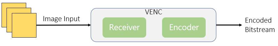
The input of VENC module is the image to be encoded and the output is the encoded Bitstream. VENC contains two sub modules, Receiver and Encoder.
Receiver
Receives image input.
Encoder
Encodes the received images into Encoded Bitstream.
The current video standards supported are:
JPEG
The supported image formats are
YUV422
YUV420
NV12 / NV21
MJPEG
The supported image format is the same as JPEG
H.264
The supported image formats are
YUV420
NV12 / NV21
H.265
The supported image formats are
YUV420
NV12 / NV21
7.2.2. VENC Channels
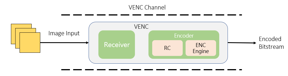
VENC channel is the basic operation unit of video encoder, which mainly includes VENC related functions and channel related settings.
The system can have multiple video encoding channels, and each channel operates independently.
After each channel is established, users can set the basic parameters of the channel according to their needs, such as image resolution, encoding Bitrate, RC mechanism, etc.
The related parameters are used to initialize VENC.
7.2.3. Rate Control
RC is the main module to control Bitrate and Video Quality in encoder.
It further controls the image quality by the parameter QP in each video standard.
When QP becomes larger, the amount of encoded data will be smaller, but video quality will be worse; When QP becomes smaller, the amount of encoded data will be larger, but Video Quality will be better.
Video encoding will usually run with RC.
If it is picture encoding (such as JPEG), this module will not be needed because there are only single images.
Mode |
MJPEG |
H.264 |
H.265 |
|---|---|---|---|
Fixed QP |
Supported |
Supported |
Supported |
CBR |
Supported |
Supported |
Supported |
VBR |
Not supported |
Supported |
Supported |
AVBR |
Not supported |
Supported |
Supported |
7.2.4. Fixed QP
Within the statistical time, all MB in the image use the same QP value.
7.2.5. CBR
The Constant Bit Rate (CBR) is a fixed bitrate, and the QP is dynamically controlled.
The Encoded Bitstream remains at the desired bitrate within a specified time interval.
The main parameters are as follows:
u32StatTime Bitrate (Statistical Time)
The time unit is second.
The encoder will statistically adjust the video quality to meet the desired bitrate within a specified time period.
When this value is smaller, the statistical interval is smaller, and the variation in image quality is relatively larger.
After each frame is compressed, it has a greater impact on the subsequent compression, and the video quality is less stable.
When this value is larger, the statistical interval is larger, and the impact of each compressed frame on the subsequent compression is relatively smaller, and the variation in image quality is smaller, resulting in a more stable video quality.
7.2.6. VBR
VBR (Variable Bit Rate) is a video encoding technique that allows for the dynamic adjustment of the overall bit rate within a set statistical time interval.
This technique allows for the bit rate to change as needed to maintain a consistent level of video quality, resulting in a more stable video stream.
u32MaxBitRate Maximum bitrate
Set the maximum bitrate that can be used within the statistical time interval.
u32MinQp
Set the minimum MB QP allows for limiting the best quality of the image without using excessive bitrate.
7.2.7. AVBR
AVBR (Adaptive Variable Bit Rate) is an adaptive version of variable bit rate encoding.
It dynamically adjusts the statistical target bit rate based on the level of motion in the scene.
The bitrate control algorithm internally detects the level of motion in the scene, and adjusts the target bitrate higher for higher motion scenes and lower for static scenes.
u32MaxBitRate Maximum bitrate
Set the maximum bitrate that can be used within the statistical time interval.
u32MinStillPercent
The target bitrate as a percentage of the maximum bitrate when the scene is in a static state.
MinBitrate = MaxBitrate*ChangePos*MinStillPercnet
The target bitrate is adaptively adjusted between MinBitrate and MaxBitrate based on the scene motion level.
U32MaxStillQp
When the scene is completely still, maxQp tends to MaxStillQp to ensure the picture quality of the still scene.
7.2.8. GOP Structure
The GOP (Group of Pictures) structure support for H.264 and H.265 is as follows:
GOP mode |
H.264 |
H.265 |
|---|---|---|
NormalP |
supported |
supported |
SmartP |
supported |
supported |
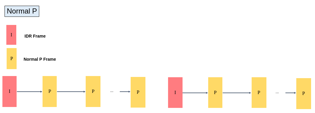
The GOP structure of NormalP is as follow:
The occurrence period of IDR frame is u32Gop
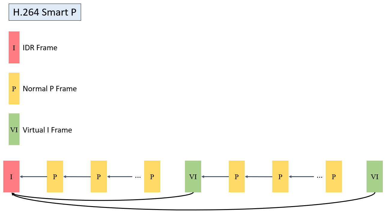
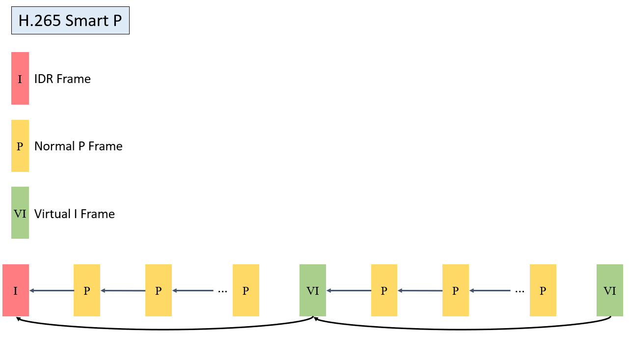
The GOP structure of SmartP is as follow:
The occurrence period of VI frame is u32Gop, which only refers to the adjacent IDR frame forward.
The occurrence period of IDR frame is u32BgInterval, which is a long-term reference frame.
7.2.9. Advanced Frame Skipping
Both H.264 and H.265 support 1, 2 and 4 times frame skipping reference modes.
The default is 1 (no frame skipping).
2 times frame skipping reference mode is shown below

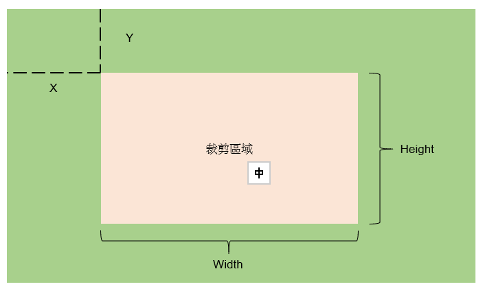
7.2.10. Cropping Encoding
For each source frame, you can only encode a certain area.
The location of the area is specified by X and Y, and the size is still specified by width and height.
Please refer to the usage of CVI_VENC_SetChnParam.
7.2.11. ROI
ROI(Region Of Interest) encoding: Region of Interest (ROI) encoding.
Users can configure ROI regions to adjust the image Qp in that area, achieving differentiated image quality for local regions in the image.
Both H.264 and H.265 support 8 ROI settings, and duplicate regions are prioritized based on the ROI index number from 0 to 7.
Absolute Qp and relative Qp can be configured in ROI area.
Absolute Qp mode: the Qp in the ROI area is the Qp value set by the user.
Relative Qp mode: the Qp in the ROI area is the Qp of the rate control plus the Qp offset value set by the user.
Note
When the rate control mode is not Fixed Qp mode, the ROI area can be configured.
When ROI is enabled in H.264, macroblock-level bitrate control is disabled.
In absolute QP mode, the actual encoded QP of macroblocks
may differ slightly from the configured QP
due to the bitrate control adjustment of macroblock QP.
7.2.12. Coding Unit (CU) Slice Mode
After compression, use CVI_VENC_GetStream to obtain Encoded Bitstream. The related information is as follows:
u32PackCount
How many NAL packets does this Frame contain?
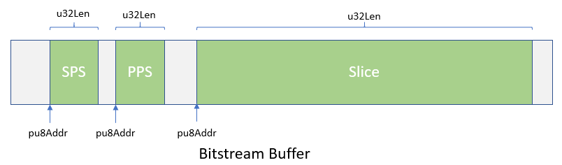
For example, the current compressed format is H.264, the first frame is I frame,
and the value will be 3 (including SPS, PPS, 1 Slice),
and the second frame will be 1(including 1 Slice).
pstPack
According to the number of u32PackCount, pstPack[0] ~ pstPack[u32PackCount - 1] data will be included.
For example, the first I Frame will have pstPack[0], pstPack[1], pstPack[2]
The following figure shows the Bitstream data of the first I Frame
7.2.13. Multi-Encoder Parallel Encoding
H.264 and H.265 support multi-encoding, with up to 8 parallel encoding as the default maximum.
The following are some points to note:
The overall performance of the code needs to be below the hardware design limit, beyond which the set framerate cannot be achieved
The required Frame Buffer will increase in proportion to the number of channels, and the DRAM usage increases accordingly.
7.2.14. The Encoding Frame Buffer Calculation
The allocation of frame buffers for reference frames and reconstructed frames in video encoding can be done using two methods: PrivateVB pool and UserVB pool.
In the PrivateVB pool method, the VENC creates a private VB pool as the buffer for reference and reconstructed frames when creating an encoding channel.
In the UserVB pool method (supported only in H.264/H.265 encoding), the reference and reconstructed frame buffers are not allocated during the creation of an encoding channel.
Instead, the user can use the CVI_VB_CreatePool interface to create the VB pool.
A video buffer VB pool can be created and then a specific encoding channel can be bound to a fixed video buffer VB pool by calling the interface CVI_VENC_AttachVbPool.
The two methods can be selected by setting the corresponding module parameters through the CVI_VENC_SetModParam interface.
Setting the module parameter to VB_SOURCE_PRIVATE indicates the use of the encoding PrivateVB pool mode, while setting it to VB_SOURCE_USER indicates the use of the encoding UserVB pool mode.
In UserVB mode, the maximum memory consumption for encoding frames is as follows
H.264 |
H.265 |
|
|---|---|---|
FrameSize |
(align(width,32)) x (align(height,32)) x 2 x 1.5 |
align((width x height x 1.5), 4096) x 2 |