4. Overview of Image Quality Tuning
Currently ISP processors are mainly targeted at IPC security scenarios, including linear and WDR modes. Due to the special needs of the security industry, the focus of IPC security scenarios on image quality is different from that of general consumer scenarios.
4.1. Overview of Image Tuning for IPC Applications
Current ISP processors for IPC security scenarios are divided into two modes: linear mode and WDR mode.These two modes focus on the dimensions of image quality, including the rationality and accuracy of the brightness and color of the image, the overall transparency and clarity of the image, and the ability to suppress noise. In addition, the dimension that WDR mode focuses on includes a reasonable dynamic range for the overall image, that is, dark details can be preserved and bright areas will not be overexposed.The following describes image quality tuning methods and Tuning principle in linear mode and WDR mode, respectively.
4.2. Image Quality Tuning in Linear Mode
Image quality tuning methods in linear mode mainly focus on four dimensions: brightness, color, transparency, sharpness and noise. Among them, modules related to brightness tuning are AE and LSC; modules related to color tuning are AWB, CCM and CLUT; modules related to transparency tuning are Gamma, Dehaze, DCI and LDCI; modules related to sharpness and noise suppression are DPC, BNR, Demosaic, 3DNR, YNR, CNR and Sharpen. The image quality tuning framework for IPC scenarios in linear mode is shown in Fig. 4.1.
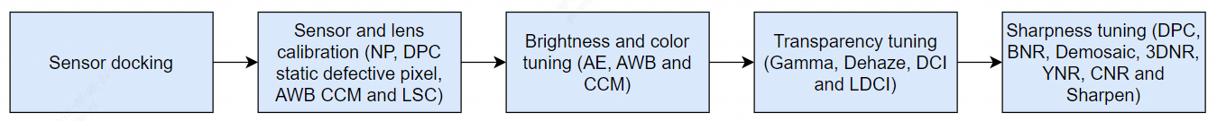
Fig. 4.1 Image Tuning Framework for Linear Mode of IPC Application Scenario
4.2.1. Sensor docking
The main task of Sensor docking is to dock the processor with Sensor such as IMX327, to confirm whether the overall path is working properly, whether the modes can be switched smoothly, whether the parameters of each module drive Sensor reasonably under the default configuration, and whether the basic functions of AE work as expected.
4.2.2. Sensor and lens calibration
The process of Sensor and lens calibration is shown in Fig. 4.2. The main steps involved include black level calibration, Noise Profile calibration, static defect pixel calibration, LSC calibration, and AWB and CCM color calibration.

Fig. 4.2 Flowchart of Sensor and lens calibration
- Black Level Calibration: The first step in the ISP overall calibration process is black level calibration. Please refer to section 5.1.1 “Black Level Calibration Method” for detailed calibration methods.
- Noise Profile calibration: After the black level calibration is completed, Noise Profile is calibrated to provide noise reduction related modules such as BNR and 3DNR. Noise Profile calibration results are obtained according to different ISOs. The range of ISO values is {100, 200, 400, 800, 1600, 3200, 6400, 12800, 25600, 51200, 102400, 204800, 409600, 819200, 1638400, 3276800}. The range of ISO values is as wide as possible. Please refer to section 5.7.1 “BNR Calibration Method” for detailed calibration methods.
- Static Defective Pixel Calibration: The static defective pixel of the Sensor includes bright and dark pixels, while the static defective pixel calibration is related to the resolution of the Sensor. Static defective pixels tables containing bright and dark pixels need to be re-calibrated for different resolutions.The calibration results are obtained according to different ISOs.
- LSC calibration: The main purpose of LSC calibration is to eliminate the dark angle of the picture caused by uneven optical refraction of the lens. The calibration method is Mesh LSC (MLSC). In low illumination, the noise of dark corner of the picture is uneven due to Shading, which can be adjusted by MeshStr. Please refer to section 5.4.1 “MLSC Calibration Method” for specific calibration methods.
- AWB calibration: The principle of AWB calibration is to extract white point information under multiple light sources, namely R/G and B/G, and calculate Planck color temperature fitting curve. Because AWB is strongly related to the Sensor and lens filters, the AWB coefficients need to be re-calibrated for each lens or filter change. Please refer to section 5.6.1 “AWB Calibration Method” for the specific calibration methods.
- CCM calibration: The main principle of CCM calibration is to calculate a 3x3 matrix, so that the actual color values obtained from the first 18 color blocks of the 24 color cards captured by the sensor are as close as possible to the expected values. Generally, the raw obtained under three light sources (D50, TL84 and A) is used to achieve the CCM calibration. Please refer to section 5.11.1 “CCM Calibration Method” for specific calibration methods.
After calibrating the sensor and lens above, the next step is to optimize the image quality of ISP modules, including the image quality optimization in different ISO settings.
Scenes to tune in linear mode include laboratory still life scenes and outdoor real-world scenes. Generally speaking, the parameters of ISP modules must be tuned for laboratory still life scenes at different illumination levels. The four dimensions of image quality, including brightness, color, contrast, sharpness and noise, should be tuned reasonably. Next, fine-tune the different actual outdoor scenes, which cover a variety of detailed scenes such as day and night, sunny and cloudy weather, and evening sunset.
Linear mode image quality is shown in Fig. 4.3 according to the tuning sequence of the four dimensions above.
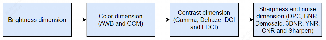
Fig. 4.3 Sequence diagram for image quality tuning
4.2.3. Brightness Dimension
For the tuning of brightness dimension, it mainly tunes AE weight table, AE Route, AE target value, convergence speed and smoothness of AE module to achieve a reasonable overall image brightness.Before tuning AE, confirm that the black level and LSC have completed the correction.
Step 1. Determine the AE weight table. For IPC scenarios, attention is generally paid to the middle area of the picture, so the middle part of the AE weight table has a higher weight than the surrounding part.
Step 2. Determine how the AE Route determines the exposure distribution. Different scenarios require different exposure times and gain allocations.
Step 3. Adjust AE target values for laboratory still scenes.It is recommended to reach the bright area without exposure as the basis.
Step 4. For different application scenarios, tune the convergence speed and smoothness of AE to achieve a balance between them.The principle of tuning is to increase the convergence speed as much as possible while preventing AE oscillation.The convergence speed and smoothness of AE can generally be tested by switching lights in a laboratory still scene.
4.2.4. Color Dimension
The tuning of color dimension mainly involves AWB and CCM.Before tuning the color, confirm that the black level and LSC calibration are complete and the AE module parameters are finished tuning.
Step 1. AWB calibration of 24 color cards using lab light box under D65, D50, A and D50 color temperature light sources for outdoor scenes to obtain white balance coefficients. In addition, more light sources such as TL84 and CWF can be added to improve the calibration accuracy.
Step 2. Using lab light box, CCM calibration is performed for 24 color cards under three light sources, D50, TL84 and A, each generating a 3x3 matrix.
Step 3. After the AWB and CCM calibration is completed, 24 color cards with different light sources are tested with Imatest to preliminarily confirm whether the calibrated AWB coefficients and CCM matrices meet the requirements.
Step 4. After preliminary confirmation of the laboratory scene, a large number of outdoor scene tests are required, covering typical scenarios such as mixing light sources, sunny and cloudy days, front-lighting and back-lighting, and evening sunset. Please refer to sections 5.6.2 “AWB Tuning Method” and 5.11.2 “CCM Tuning Method” for specific tuning methods for AWB and CCM.
4.2.5. Contrast Dimension
The main modules involved in tuning the contrast dimension are Gamma, DCI, LDCI and Dehaze. Gamma is generally the main tuning module. Before tuning the contrast, confirm that black level and LSC calibration are complete, AE module, AWB and CCM parameters are finished tuning.
Step 1. Adjust the Gamma curve with the Gamma parameters to get a better contrast for the whole image, showing details in bright and dark areas. Please refer to section 5.12.1 “Gamma Tuning Method” for specific tuning methods for Gamma module.
Step 2. If you want to further tune the contrast, the tuning principle is mainly LDCI, supplemented by DCI and Dehaze. LDCI enables local contrast enhancement and improves the performance of bright and dark areas in the picture in terms of detail. Please refer to section 5.24.1 “LDCI Tuning Method” for specific tuning methods for LDCI. For specific tuning methods for DCI and Dehaze, refer to sections 5.23.1 “DCI Tuning Method” and 5.13.1 “Dehaze Tuning Method” .
Step 3. After optimizing the parameters of Gamma, LDCI, DCI and Dehaze, test the gray scale card under the lab light box D50 to ensure the gray scale is no less than 18. Fig. 4.4 is a gray scale card diagram.
Step 4. Tune Gamma, LDCI, DCI and Dehaze appropriately for laboratory still scenes at different ISOs to achieve the desired contrast of the overall picture. In low illumination environment, it is recommended that the contrast intensity should not be too high to avoid noise enhancement.
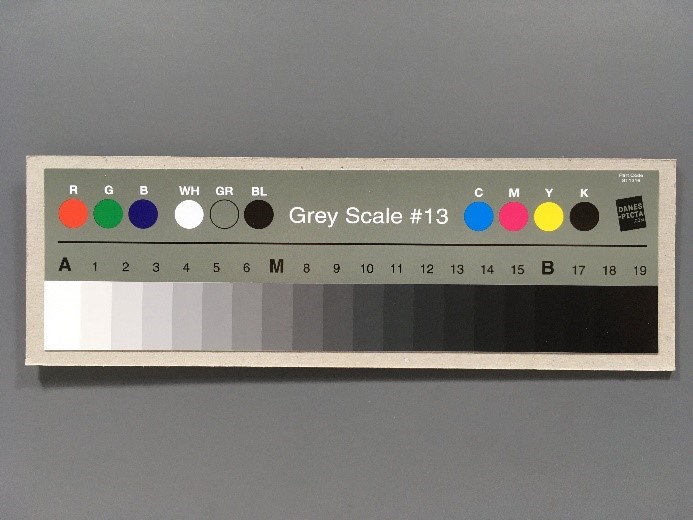
Fig. 4.4 Gray scale card diagram
4.2.6. Sharpness and noise dimensions
The main modules involved in the tuning of sharpness and noise dimension are DPC, BNR, Demosaic, 3DNR, YNR, CNR and Sharpen. Noise performance varies with illumination. Therefore, the parameters of the sharpness and noise module will be linked with ISO. For Tuning principle, it is recommended to first take sharpness as the priority, and then tune the noise reduction module if the key details and textures in the image can be satisfied. Before tuning sharpness and noise, confirm that black level and LSC calibration are complete, AE module, AWB, CCM and Gamma parameters are complete.
Step 1. First, tune the Demosaic parameters for the resolution card using the lab light box under the condition of ambient D50 light source and ISO100 until the objective requirements are met. Next, using this set of Demosaic parameters, we observe whether the lab still scene under ISO100 still meets the requirements, such as whether its high-frequency details can be interpolated, and we iterate back and forth to observe and tune it. Fig. 4.5 is a resolution card diagram. Please refer to section 5.8.1 “Demosaic Tuning Method” for specific tuning methods for Demosaic.
Step 2. Generally speaking, tuning the 3DNR first will converge the noise disturbance in the static area of the image to a stable state, and the trailing phenomenon in the moving area will be controlled reasonably. The sharpness of the whole picture can meet the requirements. Please refer to section 5.18.1 “3DNR Tuning Method” for detailed tuning methods. Next, the bright and color noise suppression of the overall image can refer to BNR (section 5.7.1 “BNR Calibration Method” ) and YNR module ( section 5.19.1 “YNR Tuning Method” ) and CNR module ( section 5.20.1 “CNR Tuning Method” ), respectively. Among them, YNR can also make further noise reduction especially for the moving area of the object to reduce the noise disturbance. It should be noted that the tuning principle of BNR and YNR is to suppress the noise perturbation of the whole picture and to show as fine fragmentation as possible after noise reduction. Therefore, it is recommended that the noise reduction intensity should not be too large to tune.
Step 3. Tuning image sharpening includes PreSharpen module before the 3DNR and Sharpen module after the 3DNR, whose parameters are all linked according to ISO. The basic tuning guideline is to properly enhance image detail texture and edge sharpness before 3DNR, but to further tune the sharpening after 3DNR without exacerbating noise. Please refer to section 5.17.1 “PreSharpen” and section 5.26.1 “Sharpen Tuning Method” for detailed tuning methods.
Step 4. If the dynamic defective pixel removal function of DPC module is in the case of good illumination, it is recommended that the intensity of relevant parameters be set to the minimum. The DPC dynamic defective pixel removal parameter is especially adjusted in a slightly lower illumination environment condition.

Fig. 4.5 Resolution Card Diagram
4.3. Image Quality Tuning in WDR Mode
Image quality tuning methods in WDR mode mainly focus on the brightness, color, dynamic range transparency and sharpness of the image, among which the modules related to brightness tuning are AE and LSC.
Modules related to color tuning, such as AWB, CCM, CA Lite, RGB CAC, CAC and CLUT.
Modules related to dynamic range tuning are WDR and DRC.
Modules related to transparency tuning are Gamma, Dehaze, DCI and LDCI.
Modules related to sharpness and noise suppression are DPC, BNR, Demosaic, 3DNR, YNR, CNR and Sharpen.
There are two typical scenarios that require the use of WDR mode, namely the brightness enhancement of faces in backlit scenes and the glare suppression scenes of neon signs and headlights at night.
An image quality tuning framework for WDR mode in IPC scenarios is shown in Fig. 4.6.

Fig. 4.6 IPC application scenario WDR mode tuning framework diagram
After completing the calibration procedure described above, the WDR mode image quality tuning is then performed for two typical application scenarios, namely the brightness enhancement of the face in the backlight scene and the glare suppression scene at night. The following describes the tuning methods for each of these two scenarios.
4.3.1. WDR mode backlight scene face brightness enhancement tuning method
The backlight scene in WDR mode is set to include a large area of light and dark areas in the image, as well as the face in the backlight, as shown in Fig. 4.7. Tuning methods to improve image quality for face brightness in backlit scenes focus on the following dimensions:
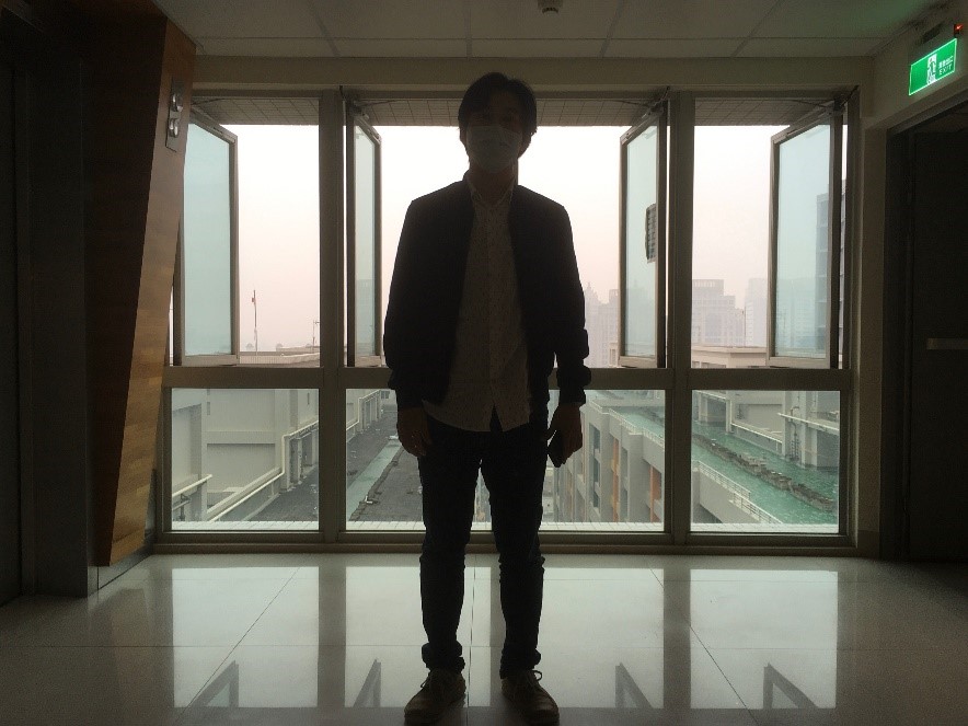
Fig. 4.7 Scene of face in backlight
4.3.2. Brightness Dimension
The brightness tuning method of WDR mode is consistent with that of linear mode as a whole. Please refer to the brightness dimension subsection of 4.1.1 “Image Quality Tuning in Linear Mode” for detailed tuning methods, but the main difference is that the exposure time of long and short frames is determined by the adjustment of AE. In addition, the exposure ratio of AE needs to be adjusted adaptively in different scenes to determine the dynamic range of WDR mode images.
4.3.3. Motion Trailing Dimension of Composite Zone
AE exposure ratio and WDR module are the main factors that affect the motion trailing of the composite area in the image. The larger the AE exposure ratio, the more likely to cause motion trailing. In typical backlight scenarios, AE exposure ratio in WDR 2-in-1 mode is 4-32 times higher than usual, in which case the WDR module is the main cause of motion trailing in the composite zone. Therefore, in the process of tuning WDR, the occurrence of motion trailing can be reduced by tuning long and short frame fusion curves and adjusting motion detection parameters. Please refer to 5.9 “WDR Tuning Method” for detailed tuning methods for WDR.
4.3.4. Dynamic Range Dimension of Scene
AE exposure ratio, DRC and Gamma modules are the main factors that affect the dynamic range of the scene. The tone mapping curve of DRC is often iteratively optimized with Gamma for the actual wide dynamic scene, adjusting the Gamma curve to increase the brightness of the backlit face in the image, while dimming the dark area to maintain its overall contrast. Next, tune the Asymmetry curve of DRC to improve the brightness of backlight face. For the specific tuning methods of DRC, please refer to 5.10.1 “DRC” .
4.3.5. Color Dimension
The method of color tuning in WDR mode is consistent with that in linear mode. Please refer to the color dimension subsection of 4.1.1 “Image Quality Tuning in Linear Mode” for detailed tuning methods.
4.3.6. Contrast Dimension
The contrast tuning methods of WDR mode are mainly DRC and Gamma, supplemented by Dehaze, DCI and LDCI, but the effect of DRC on the overall image contrast as well as the local contrast needs to be considered to adjust the brightness of the backlit faces in the image. Then, DCI and Dehaze are tuned to compensate for the lost contrast, and finally LDCI is used to enhance the local contrast.
4.3.7. Sharpness and noise dimensions
The sharpness and noise tuning methods of WDR mode is consistent with that of linear mode as a whole. Please refer to the sharpness and noise dimension subsection of 4.1.1 “Image Quality Tuning in Linear Mode” . The motion area of the image in WDR mode will tend to use long frames to reduce noise. In addition, the 3DNR and YNR parameters can be tuned together with WDR to remove the noise due to the short frames in the motion area. The steps can be described in 5.18.1 “3DNR Tuning Method” and 5.19.1 “YNR Tuning Method”.
4.3.8. Tuning Method of Intense Light Suppression Scene at Night in WDR Mode
The key application of night strong light suppression in WDR mode refers to the traffic scene at night, such as a traffic intersection or gate, etc. Fig. 4.8 shows the scene schematic diagram in the general parking lot license plate recognition application.
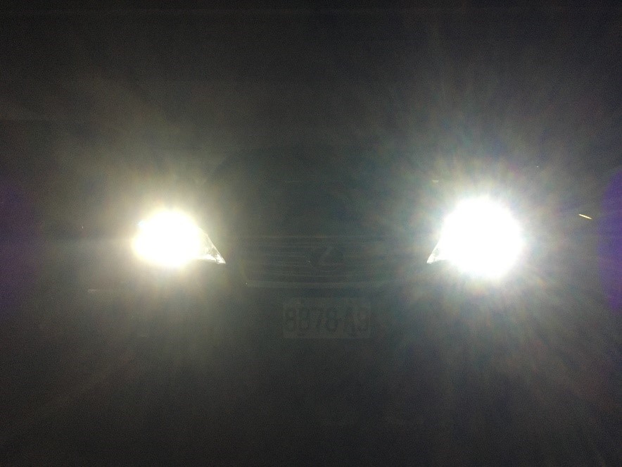
Fig. 4.8 Scene of intense light at night
Relative to backlight scenarios, the dimensions of the methods of tuning traffic scenes with night intensity suppression are as follows:
4.3.9. Brightness Dimension
The brightness tuning method of WDR mode in the night intense light suppression scene is the same as that of the backlight scene, please refer to the description of the brightness dimension of the backlight scene above for details.
However, the main difference is the effect of AE on car light halo and the effect of AE exposure time on object motion blurring.
Usually, the inside of the headlight is an overexposed area, WDR will choose short frames, while the outer halo of the headlight WDR will choose a fusion of long and short frames.
Therefore, the recommended tuning method is to configure the AE weighting table in such a way that the weighting value in the center near the headlights need to be larger than the area around the picture.
Then tune the AE target value to avoid the short frame of headlight being too dizzy.
Next, the AE Route settings limit the exposure time and use gain first to avoid motion blurring of the license plate.
4.3.10. Motion Trailing Dimension of Composite Area
The method to tune the motion trailing of the composite area for night intense light suppression in WDR mode is similar to backlight scenarios. Please refer to the above description of backlight scenarios to tune the motion trailing of the composite area.
4.3.11. Dynamic Range Dimension of Scene
The specific tuning method for the dynamic range of night intensity suppression scene in WDR mode is similar to backlight scene, please refer to the description of dynamic range of backlight scene above for tuning. It is important to note that AE exposure is about 8-16 times higher than usual at night.
4.3.12. Color Dimension
The color tuning method for night intensity suppression in WDR mode is similar to backlight scenes. Therefore, you can refer to the description of the color dimension in the backlight scene above for tuning.
4.3.13. Contrast Dimension
Contrast tuning of intense light suppression in WDR mode is similar to backlight scenes. Please refer to the description of contrast dimension of backlight scenes above for tuning. It should be noted here that DCI tuning should be avoided to make the car light halo larger, or that the adjustment of Gamma curve will make the dark area noise greater. Therefore, there is a compromise between the halo size of the car light and the dark area noise and contrast.
4.3.14. Sharpness and noise dimensions
The sharpness and noise tuning methods of intense light suppression in WDR mode are similar to backlight scenes. Please refer to the description of contrast dimension of backlight scenes above for tuning. It is important to note that the 3DNR and YNR are tuned appropriately to balance the noise and trailing in the moving area so as to avoid affecting the license plate recognition.