When the analog signal is very weak, it may not be conveyed by the analog-to-digital converter, resulting in the loss of image details when the light
is very dark.
Therefore, the image sensor will give the analog signal a fixed offset before the analog-to-digital conversion, ensuring that the output digital
signal retains more image details.
The black level correction module determines the specific value of this offset by means of calibration.
Subsequent ISP processing modules need to reduce the offset value to ensure the linear consistency of the data.
5.1.1.1. Environment and Related Equipments Preparation
If the black level parameters of the image sensor are not obtained beforehand or more accurate black level values are needed, the calibration tool
also provides a mode for automatically calibrating the black level.
Before calibration, the user needs to manually collect Raw as input for black level calibration.
The collection steps are as follows:
Step 1.
Close the device’s aperture completely or use the lens cover to block the lens input to ensure that no light enters.
Step 2.
Manually set the gain to 1x using the ExposureAttr tag of CviPQTool.
Set all OpTypes in the Exposure and Exposure Manual check boxes to OP_TYPE_MANUAL, and manually set AGain, DGain, ISP Dgain in the Exposure Manual
check box to 1024.
Step 3.
Capture a Raw file using the CviPQTool Capture Tool.
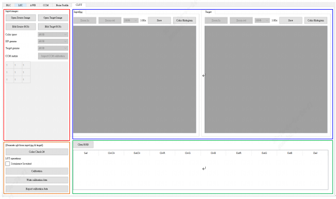
Switch the main function volume label page of the calibration tool to BLC, and you will see the interface of BLC calibration.
As shown in Fig. 5.1, the page is divided into two main parts:
Control area: The main function of the tool for calibration (red box selection area).
Display area: Display input image and result image after BLC calibration (blue box selection area).
Interface diagram of black level calibration tool
Fig. 5.1 Interface diagram of black level calibration tool
After collecting the Raw required for the calibration algorithm, the user can calibrate the automatic mode of black level according to the following
methods:
Step 1.
Import the Raw file in Open raw files at the top left of the calibration tool, then use Dark frame in the drop-down menu.
Step 2.
Click the Calibration button to calibrate the black level.
In sensor manufacturing, depending on the process yield, there will be a varying number of defective pixels.
Interpolation (Demosaic) or filter processing on the image will spread the defective pixels to the surrounding pixels.
In order to reduce the damage of defective pixels to the original pixels, the defective pixels must be corrected before image processing such as interpolation.
Defective pixels can be divided into two types:
Static defective pixels :
Bright point: Usually the pixel value is directly proportional to the brightness of the incident light source. A bright point is defined as a point whose value is much larger than that of the incident light multiplied by the corresponding ratio, and the value of this point increases significantly as the exposure time increases.
Dark point: The pixel value at this point is very close to 0 regardless of the characteristics of the original light source.
Dynamic defective pixels:
In normal usage, the pixel value at this point is normal, but it will appear brighter than the surrounding pixels due to different environmental
conditions such as usage time or sensor temperature rise and gain increase.
Detection and correction of static and dynamic defective pixels mainly use 5x5 window to determine and correct the same color channel.
The types of defective pixels DPC can support:
Single defective pixel
Defective pixels aggregation, with up to three adjacent defective pixels per color channel
Fig. 5.2 A single defective pixel, as shown below is the R defective pixel
Fig. 5.3 There are two defective pixels in the same color channel, G has two consecutive defective pixels, and R, B defective pixels will not affect the correction of G.
Fig. 5.4 Three defective pixels in the same color channel
DPC unsupported defective pixels type:
Aggregation of more than three defective pixels in the same color channel
The upper bound of the cluster defective pixels area, the higher the value, the better the correction of the cluster defective pixels, but may cause the attenuation of the resolution in the high frequency region.
BrightDefectToNormalPixRatio
[1, 255]
128
The ratio of the visible bright defective pixels value to the surrounding pixels.
DarkDefectToNormalPixRatio
[1, 255]
128
The ratio of the visible dark defective pixels value to the surrounding pixels.
FlatThreR
[0, 255]
8
Threshold value of flat area for R-channel discrimination, the smaller the value, the more edge information can be retained.
FlatThreG
[0, 255]
8
Threshold value of flat area for G-channel discrimination, the smaller the value, the more edge information can be retained.
FlatThreB
[0, 255]
8
Threshold value of flat area for B-channel discrimination, the smaller the value, the more edge information can be retained.
FlatThreMinG
[0, 255]
15
The minimum threshold value of flat area for G-channel discrimination
FlatThreMinRB
[0, 255]
15
The minimum threshold value of flat area for RB-channel discrimination
Dynamic DPC processing intensity is closely related to ISO value.
The higher the ISO, the noisier the image.
By increasing the intensity of dynamic DPC, better image quality can be obtained.
However, if the intensity is too strong, details will be lost and edges will be blurred.
Therefore, dynamic DPC intensity adjustment must be made for different sensors and different scenarios in tuning.
Parameters corresponding to 16 ISO values listed as 4.1.1 are configured in sensor’s cmos.c.
When the actual effect is not as expected, the user can tune it according to the following steps:
Step 1. Set BrightDefectToNormalPixRatio, which is twice the average value of the defective pixels in the bright area of the R/G/B pixel and
the surrounding pixels.
The default value is 4 times, which is equivalent to correcting defective pixels that are more than 4 times the average value of the surrounding
pixels.
The larger the BrightDefectToNormalPixRatio, the more accurate the defective pixels judgment condition is.
If there are any remaining defective pixels in the image, the BrightDefectToNormalPixRatio can be adjusted lower.
Note that if it is adjusted too small, the edge details will be lost.
The DarkDefectToNormalPixRatio adjustment is the same as above, which is the ratio of dark area defective pixels to surrounding pixels.
Step 2. The threshold value of flat zone is determined by adjusting the slope FlatThre[R/G/B] and the threshold value of flat zone
FlatThreMinG/FlatThreMinRB.
Take the G-channel flat area threshold as an example, as shown in Fig. 5.6, the smaller the FlatThreMinG threshold is, the better the edge
information of the image can be preserved.
The larger the threshold value of the flat area, the easier it is to judge as the flat area, resulting in loss of details on the more polygonal edges.
—-end
Fig. 5.6 Diagram of adjustment of flat zone threshold value of G-channel
Crosstalk refers to a square or similar pattern produced by a sensor after a Demosaic interpolation operation because the Gr of the neighboring pixels
is inconsistent with the Gb value due to a particular angle of incoming light.
Therefore, in order to balance the difference between adjacent Gr and Gb.
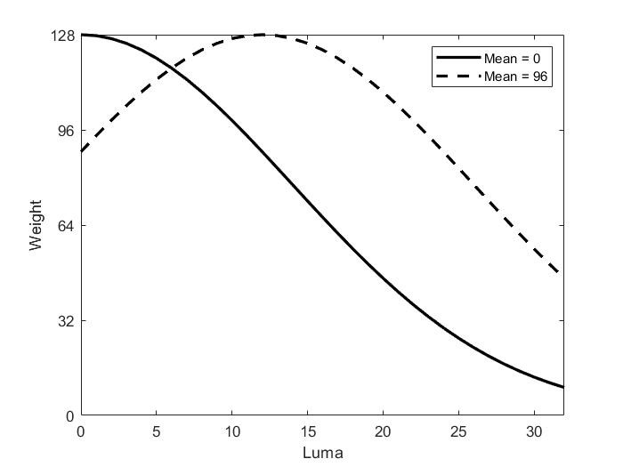
As shown in Fig. 5.7, the horizontal coordinates represent the difference between Gr and Gb, Diff = | Gr - Gb|, the vertical coordinates represent
the corresponding weight values, and T1~T4 is the Threshold value that the user can define.The smaller the difference, the larger the weight value,
and the greater the intensity of the overall image processing.
Fig. 5.8 CrossTalk Removal process flow chart and key parameters
Step 1.
By adjusting GrGbDiffThreSec1 to GrGbDiffThreSec4, the greater the value of GrGbDiffThreSec1, the stronger the overall
processing intensity.
GrGbDiffThreSec2- GrGbDiffThreSec4 determines how far the difference is from and how much the intensity is weakened.
Step 2.
By adjusting FlatThre1~FlatThre4 to determine the intensity of image edge processing, the higher the value of FlatThre1, the stronger
the edge will be processed, resulting in blurring.
Conversely, the smaller the FlatThre1, the clearer the edge will be.
Step 3.Strength represents the overall intensity of the image processing, the higher the value, the stronger the intensity;Conversely, if the value is
set too small, the lattice noise of CrossTalk will remain
It is found that in the Lens Shading phenomenon, the attenuation trend of the brightness of the target point conforms to the law of cosine fourth
power.
For the same lens module, the image brightness only changes with the imaging angle between the imaging point and the optical axis.
The change trend is that the ratio is directly proportional to the fourth power of the cosine of the imaging angle, and the ratio coefficient is determined by
the lens diameter and focal length of the lens.
Therefore, for the same lens module, the calibration results need to meet the following two conditions:
First, the calibration results can effectively reflect the brightness decay trend;Second, the calibration results can be used to restore the
brightness of all target points in the image area.
Therefore, the calibration results of this module need to be stored in a Mesh grid.
It is also important to note that even for the same lens module, the Color Shading characteristic curves are different under different light sources or color
temperatures due to the different frequency spectra of light sources or different color temperatures and the influence of IR-cut Filter.
Therefore, in order to meet the correction requirements for Color Shading under different light sources or color temperatures,MLSC needs to be
corrected at different light sources or color temperatures.
Due to the influence of Color Shading, for some lenses or sensors with more severe Color Shading phenomena, MLSC correction of AWB calibration
collection sequence is required before AWB calibration.
In order to get accurate AWB calibration results, the calibration results are used as input of AWB calibration algorithm.
5.4.1.1. Environment and Related Equipments Preparation
For the calibration of MLSC, grayscale images with multiple light sources are prepared as necessary.Explicit collection requirements are as follows:
The calibration sequence acquisition object of MLSC module must be a light source with flat and even brightness distribution, and the acquisition object must be kept smooth and textureless.Ideally, luminosity box, integrating sphere, DNP lamp box should be used for collection. Other scenarios that can be used as the collection object for MLSC calibration sequence are: lamp box grey inner wall (no obvious scratches or smudges), light source with uniform distribution through ground glass.If the conditions are limited, it can be any gray-scale plane (similar to a white wall) that achieves uniform brightness distribution, but the accuracy of the calibration may be affected.
If the object of collection is the gray inner wall of the lamp box, it is better to keep the lens pointed at the center of the light source and try to ensure that the light source distribution in the capture area of the lens is flat because there is a certain possibility that the light source of the lamp box is not evenly distributed on the inner wall.
The acquisition sequence format is RAW format, only needs 1 frame. During the acquisition process, the illumination of the light source is around 400 lux, the brightness of the lens center needs to be kept at 70% of the maximum (255), and the lens that needs to be calibrated is used.
Scenes that need to be used under different light sources need to be calibrated under different light sources. The commonly used light sources are TL84, CWF, A, D65, D50, etc. Please select a light source to calibrate according to the use requirements.
Repeated calibration is required for different lens modules
The actual preparation steps are as follows :
Step1. Aim the lens at the target area and keep the environment undisturbed
Step2. Adjust the light source brightness so that the average value of the lens center brightness is 70% of the maximum value.
Step3. Raw data is collected using the CviPQTool Capture Tool with only one frame.
Step4. Replace the light source and repeat the above steps.
—-end
The collected MLSC calibration sequence is shown in Fig. 5.9:
Switch the main function tab of the ISP calibration tool to MLSC, and you will see the interface of MLSC calibration, as shown in Fig. 5.10.
MLSC calibration tools can be divided into three main parts:
Control area: The main function of the tool for calibration (red box selection area).
Display area: Display the input image and the output image (blue box selection) after MLSC calibration.
List area: The open input images are displayed here and provide the ability to post the calibration results to the board, which is the lower left block of the MLSC tab (green box selection area).
The general steps for MLSC calibration are as follows:
Select Open raw files in the upper left to import RAW images.The imported files will be displayed on the left, then click the check box in the Sel
column to import the selected RAW images by clicking “Import selected raw” in the LSC tab.
Press the button “Calibrate” to calibrate the MLSC.MLSC calibration can support multi-color temperature and up to seven sets of MLSC calibration
tables.
LSC is called Lens shading correction, and its main purpose is to correct dark corners.The LSC algorithm in the processor uses a grid method to calibrate
the image first, then correct it, dividing the domain image on Bayer into 37×37 sub-blocks.Four channels in Bayer domain are calculated by three
different RGB gain arrays.When a MLSC array is calibrated as a complex array, an adjacent MLSC calibration table of two color temperatures is selected
based on the current color temperature for interpolation, resulting in a MLSC gain corresponding to the current color temperature.The number of groups
to be calibrated is defined by the LscGainLutSize parameter.
Before tuning parameters, verify that the modules listed in Table 5.5 have been tuned and that the default values for key parameters are configured
according to Table 5.4.
The MLSC interfaces are as follows.
The MeshShading box aggregates all the MLSC options and completes the tuning steps once the adjustment is complete.
Lens shading is due to the different refractive index of the spherical lens, resulting in concentric decay of the received image, the closer to the
center of the lens, the less the image brightness decay, and the more away from the center of the lens, the stronger the image brightness decay.
Radial Shading Correction provides concentric circle-based dark corner gain to deal with the dark corner phenomenon caused by uneven optical
refraction of the lens.
Radial shading correction is only supported for generating image corrections on AE, AWB, AF statistics.
Radial shading correction calibration is the same as MLSC, for the same lens module, the calibration results need to meet the following two
conditions: first, the calibration results can effectively reflect the luminance decay trend; second, the calibration results can be used to recover
the luminance of all target points in the image area.
At the same time, it should be noted that, due to the different spectrum of light under different light sources or color temperatures, and the
influence of IR-cut filter, the Color Shading characteristic curve under different light sources is different even for the same lens module, so in
order to meet the calibration requirements of Color Shading under different light sources or color temperatures, the RLSC needs to be calibrated under
different light sources or color temperatures.
Therefore, in order to meet the requirements of color shading correction under different light sources or color temperatures, RLSC needs to be
corrected under different light sources or color temperatures.
Due to the effect of Color Shading, for some lenses or sensors with serious Color Shading, the calibration acquisition sequence of AWB needs to be
corrected before doing AWB calibration, and the calibration result is used as input to the AWB calibration algorithm to get accurate AWB calibration
results.
5.5.1.1. Environment and Related Equipments Preparation
The calibration image of RLSC can be shared with the calibration image of MLSC.
Grayscale images of multiple light sources are necessary for pre-preparation.
The explicit acquisition requirements are as follows:
The calibration sequence acquisition object of RLSC module must be a light source with flat and even brightness distribution, and the acquisition object must be kept smooth and textureless.Ideally, luminosity box, integrating sphere, DNP lamp box should be used for collection. Other scenarios that can be used as the collection object for RLSC calibration sequence are: lamp box grey inner wall (no obvious scratches or smudges), light source with uniform distribution through ground glass.If the conditions are limited, it can be any gray-scale plane (similar to a white wall) that achieves uniform brightness distribution, but the accuracy of the calibration may be affected.
If the object of collection is the gray inner wall of the lamp box, it is better to keep the lens pointed at the center of the light source and try to ensure that the light source distribution in the capture area of the lens is flat because there is a certain possibility that the light source of the lamp box is not evenly distributed on the inner wall.
The acquisition sequence format is RAW format, only needs 1 frame. During the acquisition process, the illumination of the light source is around 400 lux, the brightness of the lens center needs to be kept at 70% of the maximum (255), and the lens that needs to be calibrated is used.
Scenes that need to be used under different light sources need to be calibrated under different light sources. The commonly used light sources are TL84, CWF, A, D65, D50, etc. Please select a light source to calibrate according to the use requirements.
Repeated calibration is required for different lens modules
The actual preparation steps are as follows :
Step1. Aim the lens at the target area and keep the environment undisturbed
Step2. Adjust the light source brightness so that the average value of the lens center brightness is 70% of the maximum value.
Step3. Raw data is collected using the CviPQTool Capture Tool with only one frame.
Step4. Replace the light source and repeat the above steps.
—-end
The collected RLSC calibration sequence is shown in Fig. 5.11:
The interface for RLSC calibration is common to the MLSC calibration interface, as shown in Fig. 5.10.
RLSC calibration tools can be divided into three main parts:
Control area: The main function of the tool for calibration (red box selection area).
Display area: Display the input image and the output image (blue box selection) after RLSC calibration.
List area: The open input images are displayed here and provide the ability to post the calibration results to the board, which is the lower left block of the LSC tab (green box selection area).
The general steps for RLSC calibration are as follows:
Select Open raw files in the upper left to import RAW images.The imported files will be displayed on the left, then click the check box in the Sel
column to import the selected RAW images by clicking “Import selected raw” in the LSC tab.
Press the button “Calibrate” to calibrate the RLSC.
RLSC calibration can support multi-color temperature and up to seven sets of RLSC calibration tables.
Radial Lens Shading principle is to process the pixels with reference to the coordinates of the surrounding pixels at the center of the lens, so it
can be used to make up for the lack of concentric circle-shaped luminance decay of the lens.
Before tuning parameters, verify that the modules listed in Table 5.7 have been tuned and that the default values for key parameters are configured
according to Table 5.6.
The RLSC interfaces are as follows.
The MeshShading box aggregates all the RLSC options and completes the tuning steps once the adjustment is complete.
Based on the white point characteristics (R/G, B/G) of sensor under several standard light sources, the best Planck color temperature fitting curve is
calculated.
5.6.1.1. Environment and Related Equipments Preparation
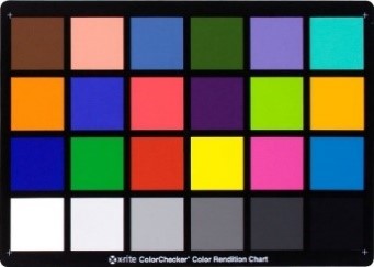
Lens and Sensors that need to be calibrated, standard 18% reflective gray card (as shown in Fig. 5.12).
Step1. Under the illumination of 600 lux (the left and right light sources should be even, and the angle between the light source and the color
card should be 25°- 45°),In choosing the type of light source, please try to satisfy the high color temperature, medium color temperature and low
color temperature in at least one group.Recommended use of D65 (6500K) or D75 (7500K), TL84 (4000K) and A (2800K) light sources
Step2. When collecting Raw, try to make the gray card picture occupy more than 70% of the picture content, and confirm that the brightness of Raw
is as expected, and the G component brightness is about 0.36 times the saturated value (if 12 bits raw, it is recommended that G value be between 1274
and 1674 ).
Only one frame can be collected, and the actual ambient color temperature needs to be recorded when collecting Raw.
Step3. Since lens shading can affect the result of AWB calibration, in order to ensure the accuracy of AWB calibration results, the collected Raws
are Shading calibrated before AWB calibration.
Step1. Import BLC Data, the correct BLC value is required to calibrate the AWB.
Step2. Click “Open raw file” to open and select the raw file you want to calibrate, and select uniform color for the Raw Scene option.
Please select the correct RAW Format to avoid calibrating the wrong AWB color temperature curve.
Step3. Check the raw file you want to label and click “Import select raw” to import it.
Step4. Repeat steps 2~3, with at least three color temperature RAW files.
Step5. Enter the color temperature (In Temp.(K)) of each RAW file in the green box area.
Step6. Check 3 KI (Key Color Temperature) in the green box area.
Step7. Click on “Calibration” to perform AWB calibration.
Step8. The blue box will show the calibrated WB curves, which can be adjusted using Weight weights.
Step9. After confirmation, press “Write Data” to write the AWB calibration data.
Step10. Click “Export Data” to export the AWB calibration file.
Step11. Note, please confirm that the higher the color temperature, the lower the value of R/G and the higher the value of B/G.
If not, please reconfirm whether the RAW shooting and format are correct.
Can be confirmed by AWB Calibration Data on the WB Attr page.
The same object will show different colors when illuminated by different light sources.
Under low color temperature light source, the white object is reddish, while under high color temperature light source, the white object is blue.The
human eye can recognize the true color of an object based on the memory of the brain.The function of the AWB algorithm is to restore white to its
original color without the influence of the light source in the field.The basic principle of AWB algorithm is to calculate the gain of R, G, B color
channels based on the color information of gray objects in the scene, multiply the gain of R and B channels, and make the RGB channels balance.The
gain of AWB is global, so the RGB three-channel balance for all gray areas cannot be achieved in a scenario with multiple light sources.
When ByPass is true, the other parameters of WB are not valid and the RGB channel gain factor is fixed to 1024 (double gain).
OpType
[0, 1]
0
Manual white balance and automatic white balance mode switch.
AlgType
[0, 1]
0
AWB algorithm category 0:AWB, 1:AWB_SPEC
AWBRunInterval
[1, 255]
6
The working frequency of white balance module, the preset value of 6 is recommended to avoid too much computation.
RGain
[1, 16383]
1024
Manual white balance mode R channel gain factor, doubling gain is 1024.
GGain
[1, 16383]
1024
Manual white balance mode G channel gain factor, doubling gain is 1024.
BGain
[1, 16383]
1024
Manual white balance mode B channel gain factor, doubling gain is 1024.
Enable
[0, 1]
1
To enable automatic white balance mode.
RefColorTemp
[0, 65535]
5000
The static white balance factor given by the AWB calibration tool.
Static WB
[0, 4096]
1024
The static white balance factor given by the AWB calibration tool.
CurvePara
[-214 7483648, 214 7483647]
1
CurvePara [0-2] Planck curve coefficients, given by the AWB calibration tool.Planck curves depict the color representation of white blocks at standard
light sources at different color temperatures.CurvePara [3-5] color temperature curve coefficient, given by AWB calibration tool.Color temperature
curves depict the relationship between the color representation of white blocks and color temperature.
AWB.AlgType
[0, 1]
1
AWB algorithm category selection,0:AWB_ALG_LOWCOST, 1:AWB_ALG_ADVANCE.
When using AWB_ALG_LOWCOST, the functionality of the AWBAttrEx page will not work.
RGStrength
BGStrength
[0, 255]
128
AWB correction intensity, adjustment is not recommended in general.RGStrength = BGStrength is recommended and set to <=0x80.
When RGStrength=0x80, the white color returns to white.
When RGStrength > 0x80, white is opposite to light source, low color temperature is blue, high color temperature is red;
New tuning mode (BGStrength=0 to enter this mode):
When RGStrength = 0x80 , no adjustment;
When RGStrength < 0x80 and tends to 0, it becomes more and more warm-toned;
When RGStrength>0x80 and tends to 255, it becomes more and more cool-toned
Speed
[0, 4095]
256
AWB convergence speed, the larger the value, the faster the AWB convergence, the greater the fluctuation amplitude per frame, the smaller the value,
the slower the AWB convergence speed and the higher the picture stability when switching light source.
ZoneSel
[0, 255]
32
When the parameter is 0 or 255, a white balance algorithm approximating the gray world is used, while the other values are used for classification
filtering to improve accuracy.
HighColorTemp
[0, 65535]
8000
The upper limit of color temperature supported by AWB, the recommended value is [8000, 15000].
The larger the upper color temperature limit, the greater the interference of blue objects on AWB.
LowColorTemp
[0, 65535]
2500
Lower color temperature limit supported by AWB, recommended at [1500, 2500].
The smaller the lower color temperature limit, the greater the interference of orange and red objects on AWB.
CTLimit.Enable
[0, 1]
1
White balance gain range limit switch.
CTLimit.OpType
[0, 1]
0
Set the gain range of white balance automatically or manually.
CTLimit.HighRgLimit
[0, 16383]
2500
Maximum R gain at high color temperature in manual mode.
CTLimit.HighBgLimit
[0, 16383]
512
Minimum B gain at high color temperature in manual mode.
CTLimit.LowRgLimit
[0, 16383]
512
Minimum R gain at low color temperature in manual mode.
CTLimit.LowBgLimit
[0, 16383]
4096
Maximum B gain at low color temperature in manual mode.
ShiftLimitEn
[0, 1]
1
Switch on which the gain of AWB exceeds the white-like point range maps back to the White-point range.
ShiftLimit
[0, 4095]
240
The white area range supported by AWB is determined with Planck curve as the center point, ShiftLimit as the top and bottom band.
ShiftLimit[0] and ShiftLimit[1] are the lower and upper band widths of the white area of 1500 ~ 4000K
ShiftLimit[2] and ShiftLimit[3] are the lower and upper band widths of the white area of 4001 ~ 4800K
ShiftLimit[4] and ShiftLimit[5] are the lower and upper band widths of the white area of 4801 ~ 6000K
ShiftLimit[6] and ShiftLimit[7] are the lower and upper band widths of the white area of 6001 ~ 15000K
Depending on the different high and low color temperature lamp sources, different sizes of bands can be set.
The larger the value, the wider the bands in white area, and the wider the support for special light sources, which will affect the AWB accuracy in
specific scenes.
GainNormEn
[0, 1]
1
Restricting the gain of RGB channels can improve the signal-to-noise ratio of low color temperature and low illumination scenes and turn it on by
default.
NaturalCastEn
[0, 1]
0
AWB style preference switch at low color temperature, light source color will be retained at low color temperature.Preset off.
CbCrTrack.Enable
[0, 1]
0
Linking parameters between AWB statistical range and ISO.
CbCrTrack.CrMax
[0, 16383]
1100
Maximum R/G at different ISOs.
CbCrTrack.CrMin
[0, 16383]
400
Minimum R/G under different ISOs.
CbCrTrack.CbMax
[0, 16383]
750
Maximum B/G under different ISOs.
CbCrTrack.CbMin
[0, 16383]
256
Minimum B/G under different ISOs.
LumaHist.Enable
[0, 1]
1
Whether different brightness turns on weight or not, preset turns on.
LumaHist.OpType
[0, 1]
0
Automatic mode:AWB assigns weights automatically.
Manual mode: Users can set brightness classification and weights themselves.
LumaHist.HistThres
[0, 255]
16
Threshold value for brightness classification (valid in manual mode).
HistThresh[0] is fixed to 0 and HistThresh[5] is fixed to 225.
HistTresh[i+1] must be greater than HistTresh[i].
LumaHist.HistWt
[0, 512]
32
Weight for brightness classification (valid in manual mode).
AWBZoneWtEn
[0, 1]
0
Picture area weight switch.It is recommended to turn on the fisheye lens or driving recorder to avoid interference from other surrounding areas.
ZoneWt
[0, 255]
8
32x32 picture weight.The center range of the picture can be weighted higher depending on the situation.
Tolerance
[0, 255]
2
The deviation range of the AWB adjustment, in which the AWB will not adjust.
ZoneRadius
[0, 255]
16
The size of the AWB statistics partition.The smaller the value, the higher the accuracy of the AWB, but it will reduce the stability of the AWB
algorithm.
CurveLLimit
[0, 1024]
320
The left boundary of the AWB color temperature curve (R/G, B/G), such as the lower left red border of the AWB analysis diagram.
CurveRLimit
[512, 16383]
768
The right boundary of the AWB color temperature curve (R/G, B/G), such as the upper right red border of the AWB analysis diagram.
ExtraLightEn
[0, 1]
0
Whether to turn on the independent light source.
LightInfo.WhiteRgain
[0, 16383]
1024
R-channel gain for special light source points.
LightInfo.WhiteBgain
[0, 16383]
1024
B-channel gain for special light source points.
LightInfo.ExpQuant
[0, 4095]
1024
Judgement based on external brightness.
ExpQuant is the brightness limit value that is turned on, for example
ExpQuant = 6, means below LV6 to open this WB light point (general night scene for below LV6)
ExpQuant = 106 means turn on above LV6
ExpQuant = 112 means turn on above LV12 (LV12 is generally outdoor)
LightInfo.Status
[0, 2]
0
The type of special light source point,
0:No action
1:Add light source point
2:Delete the calculation near the light source point.
LightInfo.Radius
[0, 255]
8
Area size of the special light source point.
InOrOut.Enable
[0, 1]
1
The parameters used by AWB to make indoor and outdoor judgments on the scene.
InOrOut.OpType
[0, 1]
0
Determine indoors and outdoors (automatic or manual).
InOrOut.OutdoorStatus
[0, 1]
0
Indoor or outdoor mode (manual mode).
InOrOut.OutThresh
[0, 20]
14
The threshold value for judging indoor-outdoor, when the brightness is less than, it is judged as indoor, and outdoor LV mostly exceeds 15.
InOrOut.LowStart
[0, 65535]
5000
Pull the weight of low color temperature down, and the starting point of low color temperature zone is suggested to be 5000K.
InOrOut.LowStop
[0, 65535]
4500
Pull the weight of low color temperature down, the end point of low color temperature zone is recommended to be 4500K.
InOrOut.HighStart
[0, 65535]
6500
Pull down the weight of high color temperature, the starting point of high color temperature zone, 6500K is recommended.
InOrOut.HighStop
[0, 65535]
8000
Pull down the weight of high color temperature, the end point of high color temperature zone, 8000K is recommended.
InOrOut.bGreenEnhanceEn
[0, 1]
1
In the green plant scenario, an additional switch is added to the green channel.
InOrOut.OutShiftLimit
[0, 255]
32
The limitation of the white point range of the AWB algorithm when judged as outdoor scenes.
MultiLightSourceEn
[0, 1]
1
AWB detects whether the current scene is a mixed light source to adjust saturation or CCM.
MultiLSType
[0, 1]
0
Adjust saturation or CCM.
MultiLSScaler
[0, 256]
256
Adjust saturation or intensity of CCM when mixed light source.
MultiCTBin
[0, 65535]
5000
The color temperature segment parameter, which must be an increasing sequence.
MultiCTWt
[0, 1024]
256
Color temperature segment weight.
FineTunEn
[0, 1]
1
AWB special color detection switch, such as skin color.
FineTunStrength
[0, 255]
128
Intensity of special color detection such as skin color and blue color.
stSkin.u8Mode
[0, 1]
0
Skin color detection switch
stSkin.u16RgainDiff
[0, 65535]
0
Skin color Rgain offset value
stSkin.u16BgainDiff
[0, 65535]
0
Skin color Bgain offset value
stSkin.u8Radius
[0, 255]
0
Skin color area size
stSky.u8Mode
[0, 2]
0: No special treatment for in-range points
1 :Remove the points within the selected range, i.e., they are not included in the calculation
2:Map Rgain and Bgain in the Radius range of the base point as MapRgain and MapBgain
0
Gray point processing mode
stSky.u8ThrLv
[0, 255]
0
Brightness threshold, the point to be processed should be greater than the current Lv
stSky.u16Rgain
[0, 65535]
0
The base point R gain of the point to be processed
stSky.u16Bgain
[0, 65535]
0
The base point B gain of the point to be processed
stSky.u16MapRgain
[0, 65535]
0
Points within the Radius range of the base point R gain are mapped to the current Rgain
stSky.u16MapBgain
[0, 65535]
0
Points within the Radius range of the base point B gain are mapped to the current Bgain
stSky.u8Radius
[0, 255]
0
The size of the region with R gain, B gain as the base point
stCtLv.bEnable
[0, 1]
0
Switch for calculating color temperature weights based on luminance
stCtLv.au16MultiCTBin
[0, 65535]
2300, 2800, 3500, 4800, 5500, 6300, 7000, 8500
Color temperature segmentation parameter, which must be an incremental sequence
stCtLv.s8ThrLv
[-128, 127]
1, 5, 9, 13
Brightness segmentation threshold
stCtLv.au16MultiCTWt
[0, 1024]
64, 256, 256, 256, 256, 512, 512, 256
Color temperature segmentation weights
stShiftLv.u8LowLvMode
[0, 1]
1
Low-light scene adjustment effective range switch
stShiftLv.u16LowLvCT
[0 x0,0xff] 0xff for full area adjustment
1:Area below the low color temperature calibration line
2:Area above the low color temperaturecalibration line
4:Area below the mid-color temperature 1 calibration line
8:Area above the mid-color temperature 1 calibration line
16:Area below the mid-color temperature 2 calibration line
32:Area above the mid-color temperature 2 calibration line
64:Area below the high color temperature calibration line
128:Area above the high color temperature calibration line
1, 192
Region for adjusting the area of the effective range from the calibration line of low brightness
stShiftLv.u16LowLvThr
[0, 65535]
15, 15
Brightness threshold for the effective range of low brightness adjustment
stShiftLv.u16LowLvRatio
[0, 65535]
150, 30
Low brightness effective range adjustment ratio (ratio/100)
stShiftLv.u8HighLvMode
[0, 1]
1
High-light scene adjustment effective range switch
stShiftLv.u16HighLvCT
[0 x0,0xff] 0xff for full area ad justment
1:Area below the low color temperature calibration line
2:Area above the low color temperature calibration line
4:Area below the mid-color temperature 1 calibration line
8:Area above the mid-color temperature 1 calibration line
16:Area below the mid-color temperature 2 calibration line
32:Area above the mid-color temperature 2 calibration line
64:Area below the high color temperature calibration line
128:Area above the high color temperature calibration line
3, 0
Region for adjusting the area of the effective range from the calibration line of high brightness
stShiftLv.u16HighLvThr
[0, 65535]
15, 15
Brightness threshold for the effective range of high brightness adjustment
stShiftLv.u16HighLvRatio
[0, 65535]
300, 100
High brightness effective range adjustment ratio (ratio/100)
stRegion.u16Region1
[0, 65535]
3900
Low, Mid1 color temperature regional demarcation point
stRegion.u16Region2
[0, 65535]
4300
Mid1, Mid2 color temperature regional demarcation point
stRegion.u16Region3
[0, 65535]
6600
Mid2, High color temperature regional demarcation point
adjBgainMode
[0, 255]
1:Low color temperature area
4:Mid-color temperature 2 area
8:High color temperature area
0
Fine-tune the area where the B gain value calculation oint is involved in white balance
Parameters:
Current AWB information can be found on the WB Info page
Parameters
Value range
Default value
Description
Rgain
[0, 16383]
0
R Channel Gain Factor of AWB Current Frame
Ggain
[0, 16383]
0
G Channel Gain Factor of AWB Current Frame
Bgain
[0, 16383]
0
B-channel gain coefficient of AWB current frame
ColorTemp
[0, 65535]
0
AWB evaluates the color temperature of the current environment
After the calibration, test the AWB accuracy under the standard light source to confirm whether the image color is correct.
In case of color deviation, it is necessary to check whether the following parameter configuration is reasonable.
Step1. Check whether the color temperature is within the range of [LowColorTemp、HighColorTemp].
If not, adjust the upper and lower limits of the color temperature.
Step2. Open the AWB analysis interface of Tuning Tools (Extra Utilities->3A Analyser ->AWB), observe whether the white point is in the white area
defined by the current parameter, if not, adjust the parameter ShiftLimit, expand the white area and summarize it.
In the AWB analysis diagram, the two green lines are the range of the current AWB color temperature curve, the AWB color temperature curve (generated
by automatic calibration) is in the middle of the green line, and the two red boxes at the bottom left and top right are CurveLLimit, CurveRLimit.
The blue dot is the R/G, B/G of each partition when the AWB screen is divided into 32x32.
Most of the blue dots fall within the range of the two green color temperature curves under the standard calibration light source.
Step3. If the lens has serious two-color problem or special application, user can turn on AWBZoneWtEn weight and fill in the corresponding weight.
Step4. If a special light source needs to be added or excluded, turn on the ExtraLightEn and there are four groups of light sources that can be
set.
After setting the relative Rgain, Bgain and Radius, Staus (when it is set to 1, this light source point will be added to improve the AWB under this
light source.
When it is set to 2, this light source will be deleted to reduce the interference of blue sky and skin color, for example.) the added or excluded
circle can be seen in the AWB analysis chart.
Step5. Outdoor color temperature weight parameter requirements: four parameters range requirements: LowStop < LowStart < HighStart < HighStop.
The following figure is an example
LowStop is 3800K, LowStart is 5000K, HighStart is 6200k, HighStop is 7200k, the general weight is 32, and the maximum weight of outdoor color
temperature is 256
Step6. In mixed light scene, if you want to use color temperature weight to improve AWB without adjusting saturation or CCM, you can turn on
MultiLightSourceEn, select SAT for MultiLSType, and set MultiLSScaler to 256.
Step7. When FineTunEn is turned on, AWB will automatically detect skin color and other special colors, improve AWB performance in skin color
scene, and improve AWB accuracy.
However, misjudgment may occur under low color temperature light source, resulting in slight yellowing of the image.
FineTunStrength adjusts the intensity of skin color detection.
The larger the value, the better the AWB performance of skin color scene, but the more obvious the side effects of misjudgment.
The default value of 128 is recommended
Place the color card in the light box. The illuminance of the light box should be set at 400 Lux. The illuminance must be uniform. After fixing the lens, adjust the distance between the lens and the 24 color card until the area covered by the color card is about 1 / 2 of the screen.
Under the same ISO, take about 20 ~ 30 frames of raw and store them in the same folder.
Adjust the aperture of the lens to the maximum, and then the user setting to measure ISO value. By adjusting the exposure time, the brightness of Block 19 at the bottom left of the 24 color card reaches 80% of the maximum value (if the image bit width is 12 bits, the brightness of Block 19 is about 3276).
Repeat Step 3-4 until all the required ISO ranges are obtained.
Note:
During the whole shooting process, please do not touch the color card and lens or walk around the shooting scene, so as to avoid the influence of light and shadow, resulting in uneven light and other problems.
After image acquisition, switch the main function tab of ISP calibration tool to BNR, and you can see the BNR calibration interface, as shown in Fig. 5.15.
BNR calibration tools can be categorized into two parts:
Control area: the main functions when performing BNR calibration (red box area).
Display area: display the input image (blue box area).
Step 1. On the Open raw files at the top left of the calibration tool, select the raw file of 24 color card, and then use 24 Colors in the drop-down menu.
Step 2. Click and import raw image of 24 color card.
Step 3. Select 24 color blocks of 24 color cards.
Step 4. Click the BLC calibration button.
Step 5. Click the LSC calibration button.
Step 6. Click BNR Calibration button to calibrate and obtain BNR calibration results.
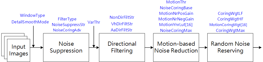
BNR is mainly used for spatial denoising in Bayer domain.
According to different sensors, the denoising model is established.
After BNR proper denoising, the final image results look natural, and avoid some common visual defects in the denoising process, such as insect noise
and pattern noise.
The configuration of key parameters provides flexibility to adjust the intensity of denoising.
At the same time of noise suppression, the edge, texture and details of the image are retained, the original noise pattern is not changed, and the
random noise is retained to a certain extent, so the signal-to-noise ratio and overall uniformity of the image results can be improved.
The local degree of denoising filter.
The smaller the value is, the more localized the action is.
CoringParamEnable
[0, 1]
0
0 :NpSlope/NpLumaThr/NpLowOffset are determined by the program;
1: The above three parameters can be set manually.
DetailSmoothMode
[0, 1]
1
To enable the de-noising detail smoothing function.
0: close
1: enable
NoiseSuppressStr
[0, 255]
0
Noise suppression intensity.
The larger the value is, the stronger the intensity of bright noise removal is.
FilterType
[0, 255]
0
Denoising filter intensity.
The larger the value is, the stronger the intensity of bright noise removal is.
VarThr
[0, 1023]
512
The threshold of edge detection. The larger the value, the less the number of judged edges.
NonDirFiltStr
[0, 31]
0
Adjust the denoising intensity in the low frequency region.
The larger the value is, the more noise is removed in the low frequency region.
VhDirFiltStr
[0, 31]
0
Adjust the denoising intensity in the horizontal and vertical areas.
The larger the value is, the more noise is removed at the horizontal and vertical edges.
AaDirFiltStr
[0, 31]
0
Adjust the denoising intensity at the diagonal edge.
The larger the value is, the more noise is removed at the diagonal edge.
CoringWgtLF
[0, 256]
0
Adjust the random noise intensity in the low frequency region.
The larger the value is, the more noise is retained in the low frequency region.
CoringWgtHF
[0, 256]
0
Adjust the random noise intensity in the high frequency region.
The larger the value is, the more noise is retained in the high frequency region.
Before tuning parameters, please confirm that the modules listed in Table 5.11 have been tuned, and the default values of key parameters are
configured according to Table 5.10.
Step 1. Adjust the brightness noise denoising function. The relevant parameters include noise suppression strength NoiseSuppressStr, and denoising filter strength FilterType. The parameters will be configured according to different ISO. First, adjust the NoiseSuppressStr to increase gradually until the whole image can keep the full details and minimize the noise. Then, increase the FilterType appropriately, and cooperate with other denoising modules to tune it.
Tuning principle: as far as possible to maintain the
uniformity of the overall image noise, and avoid impact noise, worm
noise and pattern noise. For the configuration of parameters
WindowType and DetailSmoothMode, it is recommended to use the
default value first.
Step 2. VarThr is controlled to determine the low and high frequency regions of the image, and then NonDirFiltStr and VhDirFiltStr/AaDirFiltStr are adjusted to change the denoising intensity. The larger NonDirFiltStr is, the less noise is in the low frequency region, while the larger VhDirFiltStr/AaDirFiltSrtr is, the smoother the image edge is.
Tuning principle: it is suggested that NonDirFiltStr
and VhDirFiltStr/AaDirFiltStr should be set to the same value to
denoise the whole image evenly. If the smoothness of image edge meets
the requirement, NonDirFilter and VhDirFiltStr/AaDirFiltStr are
set to 0.
Step 3. According to the low-frequency and high-frequency regions of the image obtained in step 2, the degree of random noise is retained by adjusting the parameters CoringWgtLF and CoringWgtHF respectively. Appropriately increasing CoringWgtLF can improve the worm noise and pattern noise, while appropriately increasing CoringWgtHF can increase the sense of detail.
Tuning principle: it is recommended that CoringWgtLF
and CoringWgtHF be set to the same value to make the noise of the
whole image evenly distributed. If the noise type mentioned above does
not appear in the image, CoringWgtLF and CoringWgtHF are set to
Demosaic is mainly to convert Bayer image into RGB image.
Using the relationship between the current pixel and the surrounding pixels, the direction interpolation function can be realized, and the other two
missing components are calculated.
Edge coarse tuning detection threshold.
The smaller the value is, the more edges are detected.
It is recommended to use the parameter CoarseStr for tuning.
CoarseStr
[0, 4095]
128
Edge coarse tuning strength.
The smaller the value is, the more directional the processing is.
On the contrary, the more non directional processing.
FineEdgeThr
[0, 4095]
400
Edge fine tuning detection threshold.
The smaller the value is, the more edges are detected.
It is recommended to use the parameter FineStr for tuning.
FineStr
[0, 4095]
40
Edge fine tuning strength.
The smaller the value is, the more directional the processing is.
On the contrary, the more non directional processing.
AntiFalseColorEnable
[0, 1]
0
To enable the anti-false color function
0: close
1: enable
AntiFalseColorStr
[0, 255]
255
Anti-false color Strength, the higher the value, the greater the desaturation strength.
SatGainIn[2]
[0, 4095]
[ 200, 800]
Defines the horizontal axis of the LUT, i.e.
the saturation level of the input pixels.
SatGainOut[2]
[0, 4095]
[4 095, 0]
Defines the vertical axis of the LUT, i.e., the anti-false color strength gain.
The higher the value, the greater the anti-false color strength.
ProtectColorEnable
[0, 1]
0
Enables saturation protection for custom colors
ProtectColorGainIn[2]
[0, 4095]
[20, 500]
Defines the horizontal axis of the LUT, i.e.
how similar the input pixels are to the protected color.
ProtectColorGainOut[2]
[0, 4095]
[0, 4095]
Defines the vertical axis of the LUT, which is the anti-false color intensity gain.
The smaller the value, the smaller the anti-false color intensity and the more similar it is to the input pixel.
UserDefineProtectColor1
[0, 4095]
960
To define the protection color 1.
UserDefineProtectColor2
[0, 4095]
560
To define the protection color 2.
UserDefineProtectColor3
[0, 4095]
960
To define the protection color 3.
EdgeGainIn[2]
[0, 4095]
[150, 200]
Defines the horizontal axis of the LUT, i.e.
the edge detection level.
EdgeGainOut[2]
[0, 4095]
[0, 4095]
Defines the vertical axis of the LUT, i.e., the anti-false color intensity gain.
The higher the value, the greater the anti-false color intensity.
DetailGainIn[2]
[0, 4095]
[10, 150]
Defines the horizontal axis of the LUT, i.e.
the detail detection level.
DetailGainOut[2]
[1, 4095]
[0, 4095]
Defines the vertical axis of the LUT, i.e., the anti-false color intensity gain.
The higher the value, the greater the anti-false color intensity.
DetailDetectLumaEnable
[0, 1]
1
Enable to adjust the detail detection intensity function according to the luminance.
0: close
1: enable
DetailDetectLumaStr
[0, 4095]
480
Adjusts the intensity of detail detection according to the luminance.
It is recommended to adjust it together with DetailGain.
DetailSmoothEnable
[0, 1]
0
Enables the detail smoothing function.
0: close
1: enable
DetailSmoothStr
[0, 255]
0
Detail smoothing strength.
The higher the value, the greater the smoothing strength.
DetailWgtThr
[0, 255]
0
Detail smoothing range threshold.
The smaller the value, the larger the range of detail smoothing effect.
DetailWgtMin
[0, 256]
0
The minimum gain allowed for detail smoothing strength.
DetailWgtMax
[0, 256]
256
The maximum gain allowed for detail smoothing strength.
DetailWgtSlope
[0, 1024]
256
Detail smoothing strength slope.
The higher the value, the stronger the detail smoothing strength.
64 is 1x gain.
EdgeWgtThr
[0, 255]
160
Edge smoothing range threshold.
The smaller the value, the larger the range of the edge smoothing effect.
EdgeWgtMin
[0, 256]
0
The minimum gain allowed by the edge smoothing strength.
EdgeWgtMax
[0, 256]
256
The maximum gain allowed by the edge smoothing strength.
EdgeWgtSlope
[0, 1024]
256
The slope of the edge smoothing strength.
The higher the value, the stronger the edge smoothing.
64 is 1x gain.
DetailSmoothMapTh
[0, 255]
0
Detail smoothing strength mapping range threshold.
The smaller the value, the larger the range of the edge smoothing effect.
DetailSmoothMapMin
[0, 256]
0
The minimum value allowed for detail smoothing strength mapping.
DetailSmoothMapMax
[0, 256]
256
The maximum value allowed for detail smoothing strength mapping.
DetailSmoothMapSlope
[0, 1024]
256
Detail smoothing strength mapping slope.
The higher the value, the stronger the detail smoothing strength.
64 is 1x gain.
Before tuning parameters, please confirm that the modules listed in Table 5.13 have been tuned, and the default values of key parameters are
configured according to Table 5.12.
Step 1. Firstly, the coarse edge detection threshold CoarseEdgeThr is adjusted to determine the edge range. The smaller the value, the higher the number of strong edges is judged. At the same time, the CoarseStr value is adjusted appropriately to determine the texture direction of the image and to reduce the zipper effect caused by strong edges doing the wrong direction in order to obtain the initial strong texture direction.
Tuning principle: it is recommended to start tuning
parameters from the default values of CoarseEdgeThr and
CoarseStr. Under the setting of the default value, evaluate the
smoothness and overall clarity of the edge of the image. (It is
recommended to adjust by CoarseStr before TV10, higher resolution
by FineEdgeThr to adjust)
Step 2. Then, the edge detection threshold FineEdgeThr is adjusted to determine the edge range.
The smaller the value is, the more weak edges are judged.
At the same time, edge fine-tuning strength FineStr is tuned to determine the texture directivity of the image to obtain further texture direction
confirmation.
It is recommended to match Siemens Chart/ISO12233 to observe the correct direction of the high frequency area to assist in the adjustment.
If you do not get improvement by adjusting the parameters higher, you need to check whether the CoarseEdgeThr is set too small, you can adjust the
CoarseEdgeThr higher and then observe the effect.
Tuning principle: the same as the adjustment principle
in step 1, first use the default value configuration of parameters
FineEdgeThr and FineStr to observe the current image results.
Finally, FineEdgeThr and FineStr are further adjusted
according to the demand.
Step 3. The strength of the anti-false color is controlled by the tuning parameter AntiFalseColorStr.
Also, adjust SatGainIn[2] and SatGainOut[2] to reduce false colors for low-saturation areas.
For high-frequency areas prone to false colors, you can adjust EdgeGainIn[2] and EdgeGainOut[2] to adjust the strength, as well as customize
the desired protected colors UserDefineProtectColor1~UserDefineProtectColor3 to avoid being removed as false colors, whose strength can be
controlled by adjusting ProtectColorGainIn[2] and ProtectColorGainOut[2].
Tuning principle: The parameters related to anti-false
color can be started with default values and fine-tuned as needed.
Step 4. Adjust the parameter DetailSmoothStr to reduce the false details caused by the sensor sensitivity and noise when Demosaic, which affect the
direction judgment, especially in the highly dense line texture area.
False detail suppression function can make details more natural.
The larger the DetailSmoothStr is, the stronger the detail smoothing function is.
However, too much increase will lead to the loss of detail.
As shown in Fig. 5.17, while smoothing the details, the range and strength of detail preservation are determined by the parameters DetailWgtThr
and DetailWgtSlope respectively, and the upper and lower limits of detail preservation are controlled by DetailWgtMin and DetailWgtMax.
In addition, as shown in Fig. 5.18, the parameters EdgeWgtThrand EdgeWgtSlope can be adjusted to determine the detail smoothing range and
intensity according to the edge strength, and EdgeWgtMinand EdgeWgtMax can control the upper and lower limits of the smoothing intensity.
Tuning principle: the default value of
DetailSmoothEnable is 0, that is, the smoothing function is
turned off. Interested users can enable DetailSmoothEnable and
select DetailSmoothStr to tune the smoothing intensity. Other
parameters related to the smoothing intensity will be fine tuned by
default.
Fig. 5.17 The relationship curve between detail size Detail and smoothing intensity DetailWgt during detail smoothing
Detail is the difference between the horizontal and vertical directions.
The larger the detail is, the more obvious the directivity is.
Fig. 5.18 The relationship curve between edge intensity and smoothing intensity EdgeWgt during edge smoothing
Dynamic range refers to the range of brightness difference between the brightest and darkest objects in the scene.
The larger the dynamic range, the richer the brightness levels in the scene.
The dynamic range of real scene is thousands to hundreds of thousands of times of that of image sensor.
Therefore, when using general image sensors to capture high dynamic scenes, we can only choose the low brightness area, which is easy to make the
highlight area overexposed and lose the details of the highlight area.
Or, considering the high light area, the low light area is underexposed, and the low light details are difficult to distinguish.
In order to record every detail of high dynamic range scene, it is necessary to use high dynamic range image sensor or multi exposure image synthesis.
However, due to the large area and high price of high dynamic range image sensor, its practicability is limited.
Therefore, the common way of HDR image generation is to use common sensors to obtain several fixed scene images with different exposures, and then use
WDR algorithm to synthesize a high dynamic range image.
Fig. 5.19 shows the long exposure picture, the short exposure picture, and the synthesized picture of the two in one WDR.
The short exposure image is used to capture the bright area information in the scene, while the long exposure image is used to capture the dark area
information in the scene.
After WDR synthesis, the high dynamic range image is obtained.
For the first fusion, the short exposure threshold value, above which the image data will be selected for composing WDR images with long exposure data
only.
WDRCombineLongThr
[0 , 4095]
3300
For the first fusion, the long exposure threshold value, below which the image data will be selected for composing WDR images with long exposure data
only.
WDRCombineMinWeight
[0 , 256]
32
The minimum weight value for fusing long and short exposure image data at the first fusion.
The higher the weight value, the more weight is given to long exposure during fusion, and vice versa, the more weight is given to short exposure.
WDRCombineMaxWeight
[0 , 256]
256
The maximum weight value for fusing long and short exposure image data at the first fusion.
The higher the weight value, the more weight is given to long exposure during fusion, and vice versa, the more weight is given to short exposure.
MotionCompEnable
[0 , 1]
0
To enable WDR motion detection mode switch;
0: close
1: enable
MergeModeAlpha
[0 , 255]
128
the larger the value, the more the proportion of short frame moving information is.
On the contrary, the larger the proportion of long frame moving information.
WDRMtIn[4]
[0 , 255]
[16, 64, 128, 240]
An array of four values.
Defines the amount of input object motion, the higher the value, the greater the motion.
WDRMtOut[4]
[0 , 256]
[0, 128, 224, 256]
An array of four values.
Defines the motion gain corresponding to the amount of input object motion.
The higher the value, the more it tends to output a custom WDR fusion result, which is adapted in conjunction with WDRType.
WDRType
[0 , 2]
1
Customize the WDR fusion mode:
0: Outputs short exposure value, which is multiplied by the exposure ratio.
1: Outputs long exposure value.
2: Outputs the value of the fused long and short exposures.
The weight of the long exposure is WDRLongWgt.
WDRLongWgt
[0 , 256]
128
When WDRType is set to 2, the fusion weight for long exposure is set.
Effective only when MotionCompEnable is enabled.
WDRDCMode
[0 , 1]
0
Long and short exposure fusion mode
0: General mode, adjusted by WDRLumaMode
1: DC mode
WDRLumaMode
[0 , 1]
0
Luminance calculation mode,
0: Takes the maximum value of R/G/B.
1: Takes the Luma value.
Effective only when MotionCompEnable is enabled.
WDRCombineSNRAwareEn
[0 , 1]
1
During the data fusion of long and short exposure images, the adaptive fusion weight adjustment mechanism is enabled according to the SNR of the short
exposure multiplied by the exposure ratio image.
WDRCombineSNRAwareLowThr
[0 , 65535]
1024
Low threshold value of SNR of SNR adaptive fusion weight adjustment mechanism.
When SNR is lower than the low threshold, the fusion weight will not be adjusted, but when SNR is higher than the high threshold, the fusion weight
will be adjusted.
WDRCombineSNRAwareHighThr
[0 , 65535]
8192
High threshold value of SNR of SNR adaptive fusion weight adjustment mechanism.
WDRCombineSNRAwareToleranceLevel
[0 , 255]
128
When SNR is higher than the high threshold value, the upper limit of weight is obtained.
WDRCombineSNRAwareSmoothLevel
[0 , 3000]
30
The time domain change smoothness of adaptively adjusted fusion weight.
The larger the numerical value is, the smoother the change of time domain is, and vice versa.
WDRMotionFusionMode
[0, 3]
1
Motion detection mode.
0: Linear / Long mode。
1: Max mode。
2: Merge mode。
3: LUT mode。
WDRMotionCombineLongThr
[0, 4095]
3300
Motion detection information, long exposure threshold, image data below which only long exposure data will be selected for composing WDR images.
WDRMotionCombineShortThr
[0, 4095]
3900
Motion detection information, short exposure threshold, image data above which only short exposure data will be selected for composing WDR images.
WDRMotionCombineMaxWeight
[0 ,256]
256
Motion detection information, long and short exposure image data fusion highest weight value.
The higher the weight value, the more weight is given to long exposure during fusion, and vice versa, the more weight is given to short exposure.
WDRMotionCombineMinWeight
[0, 256]
32
Motion detection information, the minimum weight value for the fusion of long and short exposure image data.
The higher the weight value, the more weight is given to long exposure during fusion, and vice versa, the more weight is given to short exposure.
LocalToneRefinedDCMode
[0, 1]
0
Whether the local tone refine refers to DC information.
0: No DC information is used, refer to LocalToneRefinedLumaMode.
Before tuning parameters, please confirm that the modules listed in the Table 5.15 have been tuned, and the default values of key parameters are
configured according to Table 5.14.
The tuning steps of WDR can be divided into tuning long and short frame fusion curves and tuning motion detection parameters.
Step 1. Tune long and short frame fusion curve, adjust WDRCombineShortThr, WDRCombineLongThr, WDRCombineMinWeight, and WDRCombineMaxWeight to generate the first fusion image. The goal is to make sure that the bright areas are not exposed and the details of the dark areas are visible.
Step 2. Tune motion fusion parameters, adjust WDRMtIn[4] and WDRMtOut[4]. The fusion ratio of the long frame to the first fused image is determined according to the object movement. The adaptation principle is that the larger the object movement is, the larger the fusion weight of the long frame is.
Step 3. Tune the motion detection parameters and adjust the WDRMotionFusionMode to maintain the integrity of the motion information in the backlit or dark areas of the screen as much as possible.
—-End
Long and short frame fusion curve
Parameters WDRCombineShortThr and WDRCombineLongThr are used to adjust the threshold value of selecting long and short frames.
Among them, WDRCombineShortThr is the threshold value of short exposure, over which only short exposure data will be selected to synthesize WDR
image; WDRCombineLongThr is the critical value of long exposure, under which only long exposure data will be selected to synthesize WDR image.
The pixels between them are synthesized by fusing long and short frames.
WDRCombineMinWeight and WDRCombineMaxWeight are the lowest and highest weight values of long and short exposure image data fusion.
The larger the weight value is, the larger the proportion of long exposure is, and vice versa.
The trend of these four parameters is shown in Fig. 5.20, with the horizontal axis representing the pixels entered as long frames.
When the WDRCombineShortThr value is set small, more pixels will select short frames, and the noise will become larger; when the value is set to a
large value in the bright area, some pixels will choose long frame fusion, which is easy to cause overexposure.
Generally, it is recommended to approach 97% of the maximum value of long exposure pixels.
If the value of WDRCombineLongThr is set to be small, more pixels choose to mix long and short frames, and the dark area noise will be larger; if
the value is set high, more pixels choose long frames, which may cause overexposure.
Generally, it is recommended to approach 80% of the maximum value of long exposure pixels.
In addition, MotionCompEnable must be turned off when adjusting the long and short frame fusion curves to avoid inappropriate adjustment due to
the influence of motion detection information.
Fig. 5.20 Selection of long and short frame threshold
Adjust motion detection parameters
The motion detection information affects the ratio of long and short frames fusion, the more obvious the object movement, the larger the motion
information, the more the object is biased towards stationary, the smaller the motion information, it is recommended to tend to use long frames in the
motion region to reduce noise.
Adjustment is recommended to give preference to the WDRMotionFusionMode of 1 to select the larger motion information among long and short frames.
SNR adaptive fusion weight adjustment mechanism
Short exposure image multiplied by exposure rate will cause some bright area noise in the picture to be over amplified.
The signal-to-noise ratio adaptive fusion weight adjustment mechanism can automatically adjust the fusion weight according to the signal-to-noise
ratio of the short exposure image multiplied by the exposure ratio, so as to increase the proportion of the long exposure image to suppress the effect
of excessive noise amplification.
When the signal-to-noise ratio is lower than the low threshold WDRCombineSNRAwareLowThr, the fusion weight is applied to the weight generated by
the long and short frame fusion curve without adjustment.
When the signal-to-noise ratio is higher than the high threshold WDRCombineSNRAwareHighThr, the upper limit weight
WDRCombineSNRAwareToleranceLevel is applied, When the SNR is between the high and low critical values, the weight generated by the long and short
frame fusion curve and the upper limit weight WDRCombineSNRAwareToleranceLevel are adjusted.
The larger the adjusted weight value is, the higher the proportion of long frame fusion is, and vice versa.
Dynamic range refers to the range of brightness difference between the brightest and darkest objects in the scene.
The larger the dynamic range, the richer the brightness levels in the scene.
Therefore, when using general image sensors to capture high dynamic scenes, we can only choose the low brightness area, which is easy to make the
highlight area overexposed and lose the details of the highlight area.
Or, considering the high light area, the low light area is underexposed, and the low light details are difficult to distinguish.
In order to record every detail of high dynamic range scene, it is necessary to use high dynamic range image sensor or multiple exposure synthesis
technology as described in 5.9“WDR” .
However, considering that the dynamic range of general display is small, in order to preserve the details of the wide dynamic image completely, it is
necessary to use DRC algorithm to compress the dynamic range of the image while retaining the details.
The purpose of DRC is to make the observer get the same visual experience when observing the high dynamic scene and the display device.
Adjustment mode; output visual auxiliary information to help users adjust;
0: do not output visual auxiliary information
3: global tone luminance display.
4: bright tone luminance display.
5: dark tone luminance display.
ToneCurveSelect
[0, 1]
0
Tone curve selection:
0: select adaptive curve.
1: select a user-defined curve.
LocalToneRefineEn
[0, 1]
0
Optimize the start of local tone mapping, making the area more finely divided.
0: Disable
1: Enable
LocalToneEn
[0, 1]
1
Bright local tone mapping and dark local tone mapping are enabled.
0: close.
1: enable.
CurveUserDefine
User-defined curves that can be pulled through control points in the UI interface
WDR/SDRHistogram
LE Histogram: Luminance statistics of long exposure images
SE Histogram: Luminance statistics of short exposure images
Global Tone Curve: Global tone mapping curve visualization
Dark Tone Curve: dark zones tone mapping curve visualization
Bright Tone Curve: bright zones tone mapping curve visualization
ToneCurveSmooth
[0, 500]
300
The smoothness of the change in the time domain of the Tone curve.
The larger the value, the smoother the change in time domain, and vice versa, the faster the change.
TargetYScale
[0, 2048]
224
Control the overall image brightness after Global tone mapping.
The first multiple is 256.
The larger the value is, the brighter the picture is; otherwise, the darker it is.
HdrStrength
[0, 255]
256
Controls the HDR enhancement effect parameter, the larger the value the stronger the overall brightness stretch, and vice versa the weaker the
stretch.
DEAdaptPercentile
[0, 25]
10
Define the dark percentile that determines the area of non-enhancement.
The larger the value, the more areas are not enhanced.
DEAdaptTargetGain
[1, 96]
40
dark tone adaptive target enhancement, the larger the value the brighter the pull, 32 for double, 40 for 1.25x
DEAdaptGainUB
[1, 255]
96
dark tone is the upper boundary of the adaptive enhancement, the larger the value the brighter the pull, 32 for double, 96 for 3x
DEAdaptGainLB
[1, 255]
16
dark tone is the lower bound of adaptive reinforcement, the larger the value the less black, 32 for double, 16 for 0.5x
BritInflectPtLuma
[0, 100]
40
Bright Tone in the short and long exposure junction area of the brightness, the larger the value, the higher the brightness
BritContrastLow
[0, 100]
50
Bright Tone dark area of the degree of darkness, the larger the value, the more darkness
BritContrastHigh
[0, 100]
80
Bright Tone bright area of the degree of brightening, the larger the value, the more pull up
SdrTargetYGainMode
[0, 1]
0
Gain Mode switch
0: Directly specify the target brightness of the screen average
1:Based on the average of the screen, pull the brightness multiplier 1x=32
SdrTargetY
[0, 255]
56
Global tone brightens the screen, the higher the value, the higher the brightness
SdrTargetYGain
[32, 128]
32
The global tone brightens the screen, and the target brightness is a multiple of the current average brightness, 1x = 32, 2x = 64
SdrGlobalToneStr
[0, 256]
256
The intensity of global tone, the larger the value, the stronger the global tone, and vice versa, the closer to the linear tone
SdrDEAdaptPercentile
[0, 32]
10
Define the dark percentile that determines the area of non-enhancement.
The larger the value, the more areas are not enhanced.
SdrDEAdaptTargetGain
[1, 64]
40
dark tone adaptive target enhancement.
The larger the value, the brighter the pull, 32 for double, 40 for 1.25x
SdrDEAdaptGainUB
[1, 255]
96
The upper bound of dark tone adaptive enhancement.
The larger the value, the brighter the pull, 32 is double, 96 is 3x
SdrDEAdaptGainLB
[1, 255]
16
The lower bound for dark tone adaptive enhancement.
The larger the value, the less darkness, 32 is double, 96 is 3x
SdrBritInflectPtLuma
[0, 100]
40
Bright Tone in the light and dark junction area of the brightness, the larger the value, the higher the brightness
SdrBritContrastLow
[0, 100]
75
Bright Tone dark area of the degree of darkness, the larger the value, the more darkness
SdrBritContrastHigh
[0, 100]
80
Bright Tone bright area of the degree of brightening, the larger the value, the more pull up
DetailEnhanceEn
[0, 1]
0
Enable Detail Enhance to enhance the details of HDR.
0: Disable.
1: Enable.
TotalGain
[0, 255]
32
Details strengthen the overall strength, 32 is double, 64 is twice
LumaGainEn
[0, 1]
0
Enable details enhance according to luma
0: Disable.
1: Enabled.
LumaGain[33]
[0, 255]
64
Weights for detail enhancement according to luma.
It consists of 33 values divided equally into 33 luminance zones, each luminance zone corresponds to a luminance weight.
The larger the value of the corresponding luminance interval, the stronger the pixel point sharpening, 64 is 1x
DeltailEnhanceMtIn[4]
[0, 255]
[0, 64, 128, 192]
An array of four values.
Defines the amount of input object motion, the higher the value, the greater the corresponding motion.
DeltailEnhanceMtOut[4]
[0, 256]
[128, 128, 128, 128]
An array of four values.
Defines the motion gain corresponding to the amount of input object motion, the higher the value the stronger the detail intensity, 256 is doubled.
OverShootThd
[0, 255]
32
White edge sharpening upper limit range
UnderShootThd
[0, 255]
32
Black edge sharpening upper limit range
OverShootGain
[0, 255]
4
Intensity of white edge sharpening, 16 for double
UnderShootGain
[0, 255]
4
The intensity of black edge sharpening, 16 for double
OverShootThrMax
[0, 255]
255
The maximum upper limit range of white edge sharpening
UnderShootThrMin
[0, 255]
255
The maximum upper limit range of black edge sharpening
Fig. 5.21 DRC processing flow chart and key parameters
Before tuning parameters, please confirm that the modules listed in Table 5.17 have been tuneged, and the default values of key parameters are
configured according to Table 5.16.
The adjustment steps of DRC are shown in Fig. 5.21.
It can be divided into adjusting local tone mapping characteristic (local tone strength), adjusting tone mapping curves (global tone mapping, local
tone mapping), and detail enhancement.
Adjust local tone mapping characteristic
The recommended order is to turn LocalToneEn off first and adjust the parameters of Global Tone Mapping to adjust the global brightness of the screen
in place, then turn on LocalToneEn to turn on local tone mapping, and after turning on local tone mapping, you can adjust dark tone for the dark areas
of the screen and adjust bright tone for the light areas of the screen to adjust the transparency.
Further, LocalToneRefineEn can be turned on to make finer corrections to the regional divisions of dark and light areas.
Tone mappingcurve adjustment
The Global Tone Mapping curve is a brightness mapping function.
The x-axis is the input brightness, and the y-axis is the output brightness.
The input and output brightness are normalized to the range of 0 ~ 1.
The general tone mapping curve is shown in:numref:Tone mapping curve illustration.
The DRC module supports tone mapping curve generation parameters, in the case of Global Tone Mapping, the curve shape can be determined by the
TargetYScale and HdrStrength parameters.
The larger the value of TargetYScale, the greater the stretching of the global tone mapping curve on the overall brightness, and vice versa, the
less the stretching of the brightness.
When the brightness of the screen is stretched too much, resulting in the dark parts of the screen are brighter, the HdrStrength can be used to
suppress the stretching of brightness, the larger the value is, the larger the stretching, the smaller the value is, the overall stretching can be
suppressed, which is more obvious with the observation of the middle and dark parts.
When Global Tone Mapping is roughly in place for the overall brightness and transparency of the picture, then adjust Dark Tone Mapping for the dark
areas of the picture and Bright Tone Mapping for the light areas of the picture.
Dark Tone Mapping curve adjustment
For the dark areas of the screen, the dark areas are adjusted by Dark Tone Mapping to present details and transparency, the Dark Tone Mapping curve is
through the statistics of the screen (histogram), to do adaptive (adaptive), mainly by DEAdaptTargetGain, to adjust the dark areas of brightness
pull up, the larger the value is, the larger the dark area is stretched, the smaller the value, the smaller the stretch.
When the dark area bright area boost, although it can present more dark details, but pull the brightness of the area close to black, may cause the
picture contrast reduced, in order to simultaneously take into account the dark area details and contrast, you can adjust DEAdaptPercentile, to
retain the contrast of the dark area, the larger the value is to retain the dark area not pulled light more, the smaller the value is to retain the
dark area less.
On the other hand, DEAdaptGainUB and DEAdaptGainLB are provided to limit the adaptive range in order to control the sensitivity of the
adaption.
Bright Tone Mapping curve adjustment
For the bright areas of the screen, Bright Tone Mapping is used to adjust the presentation of details and transparency in the bright areas.
The Bright Tone Mapping curve is used to adjust the brightness of the short and long exposure junction areas through BritInflectPtLuma, through
BritContrastLow to strengthen the contrast of the dark areas in the light area, the larger the value the stronger the contrast, the smaller the
value the weaker the contrast, through BritContrastHigh to strengthen the contrast of the light areas in the light area, the larger the value the
stronger the contrast, the smaller the value the weaker the contrast.
Visualization of curve information and statistical information
The current long-exposure histogram distribution, short-exposure histogram, and the resulting Global Tone Mapping curve, Dark Tone Mapping curve, and
Bright Tone Mapping curve can be obtained through the tool, and the information obtained is shown in the figure below.
Fig. 5.23 WDR statistical value square diagram and tone mapping curve diagram
User Define Curve
User-defined curve, currently positioned as a tune function, when the tone maping curve generated by the parameters to adjust the screen does not meet
the user’s preferences and standards, you can use the user-defined curve to observe the changes in the screen by manually stretching the curve
characteristics.
In addition, user-defined curves do not support local tone mapping.
The DRC module supports detail enhancement, which can enhance the transparency through detail enhancement.
Turn on DetailEnhanceEn to enable the detail enhancement function of DRC, adjust the intensity of overall detail sharpening through TotalGain,
and do sharpening adjustment through LumaGain for details in different brightness areas.
The rest of the parameters are designed to be consistent with PreSharpen and Sharpen modules, which can be referred to the chapters of PreSharpen and
Sharpen.
SDR DRC digital wide dynamic
SDR DRC digital wide dynamic, providing linear mode tone mapping curve adjustment, through the characteristics of local tone mapping to adjust the
local contrast of the picture, the adjustment principle is consistent with WDR mode, you can refer to the above description to make adjustments.
5.11.1.1. Environment and Related Equipment Preparation
Follow these steps to calibrate CCM:
Acquisition equipment preparation: Standard X-Rite 24 color card, illumination of 600Lux uniform light source (left and right light sources, the angle between light source and color card plane is between 25 degrees and 45 degrees), IPC.
Adjust the brightness of AE target. On the display page of PQ tool, if the G value of the 20th color block is near 201, and the G value of the 21st color block is near 163, it means that the exposure is appropriate.
The neutral gray RAW image was collected to check the degree of lens shadow of IPC. When lens shading is serious, the shading coefficient needs to be calibrated first, and the 24 color card image needs to be corrected before CCM calibration.
After image acquisition, switch the main function tab of ISP calibration tool to CCM to see the CCM calibration interface, as shown in Fig. 5.25.
CCM calibration tool can be divided into two parts:
Control area: the main function of CCM calibration (red box selection area).
Display area: display the input image (blue box selection area).
Generally speaking, the response of human eye to the spectrum is different from that of sensor RGB.
In order to make the captured image consistent with the color of human visual perception, we can use a color correction matrix to correct the cross
effect and response intensity of spectral response.
CCM calibration tool supports the pre correction of 3x3 color correction matrix for 24 color cards.
Please refer to section 5.11.1 “CCM Calibration Method” to complete CCM calibration.
Next, turn on SatEnable to observe whether the saturation of the image changes as expected under different light sources.
Gamma is mainly used for nonlinear conversion in the brightness space of the image to adapt to the output display device.
The R, G and B channels of the image are corrected using the same set of Gamma tables.
The distance between the nodes of Gamma table is the same, and linear interpolation method is used to generate the image pixels between the nodes.
When the contrast and permeability of the image need to be optimized, we can try to adjust the Gamma module to improve it.
Used to control the shape of Gamma curve generation.
SlopeAtZero
[0.001, 20]
20
Used to control the slope near the zero point of Gamma.
Control PointsNum
[2, 32]
2
Points for manually dragging the curve
Auto Gamma
Different Gamma curves can be set according to different ambient brightness.
GammaTabNum
[1, 5]
4
Number of Auto Gamma tables
5.12.1.3. GammaCOEFFI and SlopeAtZero Parameter Description
According to different scenes, the parameter GammaCOEFFI is adjusted to control the shape of gamma curve, and the parameter SlopeAtZero is
used to control the slope near the zero point of Gamma.
The impact of the two parameters on the shape of gamma curve is as follows:
In the case of the same SlopeAtZero, the slope of the curve near the zero point is the same, and the shape of the curve varies with the parameter GammaCOEFF, as shown in the figure below.
In the case of the same GammaCOEFFI, the overall shape of the curve remains unchanged, but the slope near the zero will vary with the parameter SlopeAtZero, and there will be a slight offset. The overall change trend is shown in the figure below.
Dehazing algorithm is mainly used in the scene with fog to improve the contrast and color saturation of the image and increase the clarity of the
scene.
The dehazing algorithm estimates the concentration of fog by calculating the statistical value of image content, and adaptively adjusts the intensity
of dehazing.
Used to control the intensity of dehaze.
The larger the value is, the stronger the dehazing intensity is.
MinTransMapValue
[0, 8191]
819
The minimum permitted transmission coefficient.
CumulativeThr
[0, 16383]
1024
The statistical threshold of haze concentration was calculated.
The default value is about 0.05% of the total number of images in the original image.
DehazeLumaEnable
[0, 1]
0
Adjust the dehazing intensity function according to the brightness to enable.
0: Disable.
1: Enable.
DehazeSkinEnable
[0, 1]
0
Adjusts the dehazing intensity function to enable according to the skin tone.
0: Disable.
1: Enable.
SkinCb
[0, 255]
124
Customize the skin color coordinates on the Cb domain.
SkinCr
[0, 255]
132
Customize the skin color coordinates on the Cr domain.
AirLightMax
[0, 4095]
4013
Airlight’s maximum allowable value.
AirLightMin
[0, 4095]
3276
Airlight’s minimum allowable value.
AirLightMixWgt
[0, 32]
0
Airlight blending weight
AirlightDiffWgt
[0, 16]
0
Airlight
DehazeLumaCOEFFI
[0, 255]
0.5
According to the brightness control dehazing intensity curve, the brightness is divided into 16 steps.
The higher the value, the stronger the dehazing intensity.
DehazeSkinCOEFFI
[0, 255]
0.25
The dehazing intensity curve is controlled according to skin tone, and the brightness is differentiated into 16 steps.
The higher the value, the stronger the dehazing intensity.
DehazeWgt
[0, 32]
0
Dehaze output blending weight
TransMapScale
[0, 255]
16
Transmission coefficient gain.
TransMapWgt
Wgt
Sigma
Wgt: [0, 128]
Sigma: [1, 255]
Wgt: 64
Sigma: 96
The transmission coefficient gain control determines the weight curve of the Dehaze result blended with the original image; the larger the Wgt,
the larger the proportion of the original image blended; the larger the Sigma, the larger the number of pixels blended with the original image.
For the image of foggy scene, the parameter Strength is adjusted according to the demand to improve the contrast and clarity of the whole image.
In principle, except Strength, other parameters can be configured according to the recommended default values.
Description
The stronger the dehazing intensity is, the higher the overall contrast and color saturation of the image will be, and the details of the dark area may be lost. Therefore, user should make a compromise parameter tuning according to the actual scene.
After dehazing is enabled, in order to make the screen display normally, two frames are delayed
The parameters DehazeLumaCOEFFI and DehazeSkinCOEFFI are adjusted separately to control the shape of the generated curves according to the
brightness and skin tone, both curves are adapted in the same way and similar to Gamma.
Taking DehazeLumaCOEFFI of 0.45 as an example, the effect on the shape of the curve is shown below.
Before doing parameter tuning, make sure that the modules listed in Table 5.22 have been tuneged and that the default values of key parameters are
configured according to Table 5.21.
Step 1. Adjusting EdgeGlobaGain to determine the total intensity gain of the edge detection. If you only need to correct the purple edges at the strong edges, you can adjust EdgeGainIn[2] and EdgeGainOut[2] appropriately to increase the gain value corresponding to the strong edges.
Step 2. Adjusting the PurpleDeRange to determine the extent to which purple edges are detected. Increase PurpleDeRange appropriately so that areas with significant purple edges in the highlights can be detected. If it is found that the normal purple color is corrected out of the highlighted areas of the image, then decrease the PurpleDeRange to protect the normal purple areas.
Tuning principle: Default values are recommended for PurpleCb/PurpleCb2/PurpleCb3, PurpleCr/PurpleCr2/PurpleCr3, GreenCb and GreenCr. Interested users only need to fine tune the default values for PurpleCb/PurpleCb2/PurpleCb3, PurpleCr/PurpleCr2/PurpleCr3.
Step 3. After the detection parameters have been configured by the above steps, DePurpleStr can be adjusted to determine the correction intensity of the purple edge as required. Further, DePurpleCrStr and DePurpleCbStr can be adjusted to determine the correction intensity of R and B channels respectively.
Tuning principle: Note that if DePurpleStr is set too high, making the correction intensity too strong, it is likely to cause significant graying at the purple edge. Therefore, it is sufficient to adjust DePurpleStr to an acceptable correction intensity for the purple border. Alternatively, you can adjust DePurpleStrMax and DePurpleStrMin to achieve the desired correction intensity.
R channel purple edge correction gain.
32 for 1x gain.
DePurpleCbGain
[0, 4095]
32
B channel purple edge correction gain.
32 for 1x gain.
DePurpleCrStr0
[0, 64]
32
Long frame R-channel correction intensity.
DePurpleCbStr0
[0, 64]
32
Long frame B-channel correction intensity.
DePurpleCrStr1
[0, 64]
32
Short frame R-channel correction intensity.
DePurpleCbStr1
[0, 64]
32
Short frame B-channel correction intensity.
FilterTypeBase
[0, 3]
0
Filter selection.
The larger the value, the stronger the de-purple edge strength.
EdgeGainBase0
[0, 64]
28
Strength gain for long frame edge detection.
EdgeGainBase1
[0, 64]
35
Strength gain for short frame edge detection.
EdgeCoringBase
[0, 255]
0
Noise suppression control for edge detection.
FilterTypeAdv
[0, 3]
0
Advanced filter selection.
The larger the value, the stronger the de-purple edge intensity.
EdgeGainAdv0
[0, 64]
28
Advanced intensity gain for long frame edge detection.
EdgeGainAdv1
[0, 64]
35
Advanced intensity gain for short frame edge detection.
EdgeCoringAdv
[0, 255]
0
Noise suppression control for edge detection.
EdgeWgtBase
Wgt
Sigma
Wgt: [0, 128]
Sigma: [1, 255]
Wgt: 96
Sigma: 76
The degree of purple edge removal is controlled by the edge intensity, which determines the weight curve for blending the result with the original
image; the larger the Wgt, the smaller the percentage of the original image is blended; the larger the Sigma, the more pixels are blended with the
original image.
EdgeWgtAdv
Wgt
Sigma
Wgt: [0, 128]
Sigma: [1, 255]
Wgt: 80
Sigma: 64
The degree of purple edge removal is controlled by the edge intensity, which determines the weight curve for blending the result with the original
image; the larger the Wgt, the smaller the percentage of the original image is blended; the larger the Sigma, the more pixels are blended with the
original image.
Fig. 5.30 LCAC processing flow chart and key parameters
Before doing parameter tuning, make sure that the modules listed in Table 5.24 have been tuneged and that the default values of key parameters are
configured according to Table 5.23.
Step 1. First, adjust EdgeGainBase to determine the intensity gain of edge detection. If you only need to correct the purple edge at the strong edge, you can adjust EdgeWgtBase.Wgt and EdgeWgtBase.Sigma appropriately to increase the gain value corresponding to the strong edge, the former controls the maximum value of edge detection intensity and the latter determines the range of edge detection.
Tuning Principle: EdgeGainBase, EdgeWgtBase.Wgt and EdgeWgtBase.Sigma are recommended to take the default value first and jump directly to step 3. If the result is not yet as expected, you can start the adjustment from EdgeGainBase first.
Step 2. The tuning principle is the same as step 1, starting with step 3. EdgeGainAdv, EdgeWgtAdv. Wgt and EdgeWgtAdv. Sigma suggest that the default values can be taken first. Depending on your needs, you can start with EdgeGainAdv first.
Step 3. Adjusting DePurepleCrGain and DePurepleCbGain to determine the intensity of the purple edge correction for the R and B channels, respectively.
Tuning principle: In WDR mode, DePurpleCrStr0, DePurpleCbStr0, DePurpleCrStr1 and DePurpleCbStr1 can be adapted to determine the R-channel and B-channel correction strength for long and short frames, respectively. In addition, FilterTypeBase and FilterTypeAdv control the intensity of the de-purple edge, generally using the default values first and starting to adapt as needed.
CLUT calibration is to establish 3D image table between input image and target image with 24 color card or user-defined source and target color pair
provided by user.
CLUT algorithm will image the image pixel by pixel to meet the needs of users for color adjustment.
The purpose of calibration is to determine the three-dimensional shift components of CLUT for various colors by RGB pairs of input image and target
image.
5.16.1.1. Environment and Related Equipment Preparation
Standard 24 color card
Uniform light source (D50 or D65 light box)
Device to be calibrated and target calibration device
Fix the lens and adjust the distance between the lens and the color card to make the color card cover at least 1/2 of the imaging screen.
Switch the main function tab of ISP calibration tool to CLUT to see the interface of CLUT calibration.
The calibration interface consists of four parts
Image control area: Control function for input images when performing CLUT calibration (red box selection area).
It contains project fonctions:
Select the image to be calibrated ( Support jpg and bmp image files.)
Locate the position of the color block of the image file to be calibrated
Select target image document ( Support jpg and bmp image files.)
Locate the color block position of the target image file
Display image area: Displays the contents of the read calibration file with the color block range (blue boxed area).
CLUT control area: The main control item (orange boxed area) when performing a CLUT calibration.
It contains the buttons:
Color selection button, confirm the color block positioning is complete, then press to obtain color block information
Constant brightness option, which can be checked according to the input image (If you do not want the CLUT to perform luminance correction you can check this item and the internal algorithm can be adjusted to reduce the effect of the CLUT on luminance tuning. It is recommended to align the brightness of the calibration file with the target file beforehand to reduce the impact of the algorithm on the color block due to the brightness alignment behavior.)
Calibration button for CLUT calibration
Write calibration data, write the corrected CLUT information to the board side
Export calibration data, save the corrected CLUT information to disk
RGB Color Pair Area: Displays color information for the calibrated color block (green boxed area).
Since the brightness, white balance, Gamma curve, CCM parameters and shading of the image may affect the accuracy of the CLUT calibration, before the
CLUT calibration, it is necessary to ensure that the AWB, brightness and gray scale of the device to be calibrated and the target device are in
accordance with each other and the Shating correction is performed before the CLUT calibration is carried out.
Step 1. The D50 or D65 lightbox illumination provides approximately 600lux illumination for shooting with the device to be calibrated and the target device against a 24-color card, and the file can be acquired by the CviPQTool Preview function to generate a BMP file or by a back-end streaming program for image acquisition (BMP or JPG file).
Calibration principle: It is recommended that the image be obtained from the back-end streamer or the final output to align with the target device.
Step 2. Since most of the target devices are not capable of brightness fine tuning, and different devices have different brightness tuning strategies, we need to manually fine tune the device to be calibrated to achieve the brightness-to-target result (this action is mainly for the CLUT to correct only the color tones without brightness correction, and the alignment of brightness needs to be adjusted by other modules), when performing the brightness-to-target action The value of the G-channel of the 21st color block in the 24-color card can be obtained by adjusting the exposure function of the device
to be calibrated for fine-tuning (such as EvBias item or gain item), and it will be completed when the value of the G-channel of the 21st color block
and the screenshot of the target device are in close agreement.
Calibration principle: It is recommended that color cards be obtained by selecting scenes that are as bright as possible. You can refer to the 19th color block in the 24 color card and suggest that its RGB value is above 240 in order to obtain better correction results.
Step 3. Click the “Open Source Image” and “Open Target Image” buttons to load the image files taken by the device to be calibrated and the target device.
Step 4. Click the “Edit Source ROIs” and “Edit Target ROIs” buttons to check the color block of the image to be calibrated and the target image.
Step 5. Generate the corresponding color pairs. Press the “Color Check 24” button to extract the color block information selected in the previous stage to the RGB color pair area.
Step 6. “Luminance Invariant” option can be checked according to the input image. This option allows the algorithm to perform pre-processing to uniformly adjust the input color block to the brightness part of the target block, in order to reduce the effect of CLUT on the brightness tuning.
Calibration principle: It is recommended to align the brightness of the calibration file to the target file and turn off this option to reduce the impact of the algorithm on the color block by performing brightness alignment.
Step 7. Click on the “Calibration” button and wait a few minutes for the CLUT calibration parameters to be generated inside the tool.
Step 8. Apply the generated CLUT to the device to be calibrated to confirm the effect of the color adjustment (write directly to the board via the “Write calibration data” button) or export the CLUT calibration contents via the “Export calibration data” button.
Fig. 5.32 Standard 24 color card No.19 (blue circle) and color block No.21 (red circle)
Provide the preferred color adjustment function, by doing 17x17x17 3D LUT to linear RGB space to achieve the adjustment of preferred colors, such as
green, blue, skin tone refinement adjustment.
Fig. 5.33 ACM processing flow chart and key parameters
Before tuning parameters, please confirm that the modules listed in Table 5.26 have been tuneged, and the default values of key parameters are
configured according to Table 5.25.
The PreSharpen module is used to enhance image sharpness and is located before 3DNR to sharpen edges and detailed textures in images.
Multiple intensity combinations in different frequency bands allow for a variety of styles of sharpness enhancement, while also providing sharpened
white edge white point (Over Shoot) and black edge black point (Under Shoot) suppression.
Fig. 5.34 shows the system framework of the Sharpen module, with the data flow diagram in black and the open parameter interface in blue.
Fig. 5.34 System framework of the PreSharpen module
※It consists of 33 values divided equally into 33 luminance zones, and each luminance zone corresponds to a luminance weight.
The smaller the value of the corresponding luminance band, the weaker the pixel sharpening
LumaCorLutIn[4]
[0, 255]
[0, 64, 128, 192]
luma-based coring, this is the input node, enter luma.
LumaCorLutOut[4]
[0, 255]
[1, 1, 1, 1]
Luma-based coring, this is the output node that outputs the corresponding coring value.
MotionCorLutIn[4]
[0, 255]
[0, 64, 128, 192]
Motion-based coring, this is the input node and the input is luma.
MotionCorLutOut[4]
[0, 255]
[8, 8, 8, 8]
Motion-based coring, this is the output node that outputs the corresponding coring value.
MotionCorWgtLutIn[4]
[0, 255]
[0, 64, 128, 255]
Adjusting the weight of luma coring and motion coring based on motion, this is the input node and enter the size of the input motion.
MotionCorWgtLutOut[4]
[0, 255]
[0, 32, 64, 128]
Adjusting the weight of luma coring and motion coring based on motion, This is the output node that outputs the weight of the motion coring.
(max = 128)
DeltaAdpGainEn
[0, 1]
0
To enable sharpness sharpening weights
DeltaAdpGain[33]
[0, 63]
32
Sharpness sharpening weights
※It consists of 33 values divided equally into 33 sharpening zones, and each sharpening zone corresponds to a sharpening weight.
The larger the value of the corresponding sharpening interval, the stronger the pixel point sharpening.
GlobalGain
[0, 255]
32
Global sharpening weight.
※The higher the value, the stronger the sharpening.
OverShootGain
[0, 255]
4
Multiplier for the upper magnitude of white edge sharpening.
(1x = 16)
UnderShootGain
[0, 255]
4
Multiplier for the upper magnitude of black edge sharpening.
(1x = 16)
OverShootThr
[0, 255]
32
White edge sharpening upper limit magnitude.
UnderShootThr
[0, 255]
32
Black edge sharpening lower limit magnitude.
OverShootThrMax
[0, 255]
255
Maximum upper limit magnitude of white edge sharpening.
UnderShootThrMax
[0, 255]
255
The maximum lower limit magnitude of black edge sharpening.
HFBlendWgt
[0, 255]
128
Weight of high frequency edge enhancement
MFBlendWgt
[0, 255]
128
Weight of mid-frequency edge enhancement
NoiseSuppressEnable
[0, 1]
1
Edge enhancement is done for edge-detected images after pre-processing with enhanced denoising.
MotionShtGainIn[4]
[0, 255]
[0, 64, 128, 192]
The LUT that determines the degree of edge enhancement for the motion area, this is the horizontal node and the input value is the motion value.
MotionShtGainOut[4]
[0, 128]
[128, 128, 128, 128]
The LUT that determines the degree of edge enhancement for the motion area, this is the vertical node and the output value is the enhancement
intensity corresponding to the motion.
SatShtCtrlEn
[0, 1]
1
Enables edge enhancement by saturation adjustment.
0: Disable
1: Enable
HueShtCtrl[33]
[0, 63]
[16, …, 16]
Edge enhancement based on specified color
SatShtGainIn[4]
[0, 255]
[0, 8, 16, 192]
Do edge enhancement based on the specified saturation, this is the input node, input saturation.
SatShtGainOut[4]
[0, 128]
[0, 0, 128, 128]
Based on the specified saturation to do edge enhancement, this is the output node that outputs the edge intensity corresponding to the saturation.
SoftClampEnable
[0, 1]
0
Enables Smooth processing edge enhancement
0: Disable
1: Enable
SoftClampLB
[0, 255]
1
Smoothing handles the upper and lower bounds of edge enhancement.
The larger the value set, the more continuous the edge enhancement will be, but the weaker the enhancement will be.
SoftClampUB
[0, 255]
1
Smoothing handles the upper and lower bounds of edge enhancement.
The larger the value set, the more continuous the edge enhancement will be, but the weaker the enhancement will be.
Before tuning the parameters, make sure that the modules listed in Table 5.28 have been tuned and that the default values of the key parameters are
configured according to Table 5.27.
The input image is pre-processed for noise removal, NoiseSuppressEnable is to enable the pre-noise removal processing mode.
Coring value adjustment
Coring value can be adjusted by LumaCorLut[4] for the static zone coring value, while the moving zone part is adjusted by MotionCorLut[4], and
finally MotionCoringWgtLut[4] decides the combined weight of static zone coring value and dynamic zone coring value according to the amount of
movement.
Edge combination for different frequency bands
For the edge to be enhanced, it can be subdivided into the high-frequency detail area and the mid-frequency edge information, and the intensity of the
high-frequency detail can be adjusted through HfBlendWgt and the intensity of the mid-frequency edge through MfBlendWgt.
Adjustment of edge strength
The adjustment of edge intensity is divided into GlobalGain, DeltaGain, LumaGain, and MotionGain, and adapting GlobalGain enhances the overall
sharpening level.
Adjusting DeltaAdpGain sets the sharpening weight according to the edge strength of the pixel.
In areas where the edge strength is strong enough, the degree of sharpening itself is high, so you can set a smaller weight to avoid over-sharpening
the image.
In areas with weak edges, set a large weight to enhance sharpening of weak texture areas.
Adjust LumaAdpGain to set the sharpening weight according to the brightness of the pixel.
In low luminance areas, the human eye is more sensitive to pixel differences, so the sharpening weight can be set smaller.
In high luminance areas, the human eye is less sensitive to pixel differences, so the sharpening weight can be configured to be larger.
The LUT input and output nodes of MotionShtGainIn [4] and MotionShtGainOut [4] are adapted.
MotionShtGainIn is the input node, representing the amount of object movement, and MotionShtGainOut the amount of object movement corresponds
to the degree of image edge enhancement, which can be fine-tuned for the edge intensity of the moving region, and the intensity of the edge can be
gradually adjusted down in the larger moving region to enhance the visual sense of continuity.
Amplitude control (Shoot Control)
The amplitude of the edges can be adjusted by OverShhotGain, UnderShhotGain, OverShootThr, UnderShootThr, OverShootThrMax, UnderShootThrMax, and turning down OverShhotGain,
UnderShhotGain, OverShootThr, UnderShootThr can reduce the white spots (Over Shoot) and black spots (Under Shoot) caused by over-sharpening.
As shown in Fig. 5.35, the higher the value of ShootThr, the greater the sharpening, but relatively speaking, it is also easy to find white and
black dots on the image.
In addition, you can control OverShootThrMax / OverShootThrMax to limit the maximum value of ShootThr.
3DNR is mainly used in YUV domain for time-domain denoising.
The degree of motion of the object is classified, and the denoising model is established according to the degree of motion.
After 3DNR denoising, the jumping random noise can be effectively suppressed, and the picture is cleaner.
Because 3DNR is a noise reduction method in time domain, it will produce drag shadow in processing, which will be aggravated on moving objects.
The configuration of key parameters provides the configuration of motion strength and de-noising intensity of 3DNR de-noising model.
At the same time, the state protection mechanism is added to weaken the performance of tailing.
Noise immunity during motion detection, the higher the value, the stronger the noise immunity, but the less detailed the detection.
MtFiltMode
[0 , 1]
1
Motion detection filter mode.
MtFiltWgt
[0 , 256]
128
Motion detection filter weight.
TuningMode
[0 , 1]
0
Motion Map switch
0: close
1: open
In Motion Map, the brighter the pixel, the greater the amount of motion, and the darker the pixel, the smaller the amount of motion.
TnrMtMode
[0 , 1]
0
Motion mode:
0: Motion IIR
1: Motion history
YnrCnrSharpenMtMode
[0 , 1]
1
Motion mode:
0: Motion IIR
1: Motion history
PreSharpenMtMode
[0 , 1]
0
Motion mode:
0: Motion IIR
1: Motion history
ChromaScalingDownMode
[0 , 3]
0
chroma scaling down
0: avg
1: drop even
2: drop odd
3: drop toggle
RNoiseLevel
[0 , 255]
16
The dark noise tolerance of R pixel.
The larger the value is, the more tolerant the noise is.
At this time, the moving information of the static region disturbed by noise is easier to be judged as stationary, which can improve the effect of
3DNR noise reduction.
If the value is too high, the small moving area will be judged to be stationary, and the 3DNR noise will appear motion drag.
GNoiseLevel
[0 , 255]
16
The dark noise tolerance of G pixels.
The larger the value is, the more tolerant the noise is.
At this time, the moving information of the static region disturbed by noise is easier to be judged as stationary, which can improve the effect of
3DNR noise reduction.
If the value is too high, the small moving area will be judged to be stationary, and the 3DNR noise will appear motion drag.
BNoiseLevel
[0 , 255]
16
The dark noise tolerance of B pixels.
The larger the value is, the more tolerant the noise is.
At this time, the moving information of the static region disturbed by noise is easier to be judged as stationary, which can improve the effect of
3DNR noise reduction.
If the value is too high, the small moving area will be judged to be stationary, and the 3DNR noise will appear motion drag.
RNoiseHiLevel
[0 , 255]
16
The brightness noise tolerance of R pixel.
The larger the value is, the more tolerant the noise is.
At this time, the moving information of the static region disturbed by noise is easier to be judged as stationary, which can improve the effect of
3DNR noise reduction.
If the value is too high, the small moving area will be judged to be stationary, and the 3DNR noise will appear motion drag.
GNoiseHiLevel
[0 , 255]
16
The brightness noise tolerance of G pixel.
The larger the value is, the more tolerant the noise is.
At this time, the moving information of the static region disturbed by noise is easier to be judged as stationary, which can improve the effect of
3DNR noise reduction.
If the value is too high, the small moving area will be judged to be stationary, and the 3DNR noise will appear motion drag.
BNoiseHiLevel
[0 , 255]
16
The brightness noise tolerance of B pixel.
The larger the value is, the more tolerant the noise is.
At this time, the moving information of the static region disturbed by noise is easier to be judged as stationary, which can improve the effect of
3DNR noise reduction.
If the value is too high, the small moving area will be judged to be stationary, and the 3DNR noise will appear motion drag.
L2mIn00~L2mIn03(L2mCurve)
[0 , 4095]
[400, 600, 1000, 2000]
An array of four numeric values.
Define the gray level, the larger the value, the higher the gray level.
L2mOut00~L2mOut03(L2mCurve)
[0 , 63]
[63, 16, 16, 16]
An array of four numeric values.
Define the motion gain, the larger the value is, the stronger the amplitude of motion judgment is.
TnrStrength
[0 , 255]
16
Motion Map amplification factor
16: 1x
32: 2x
64: 4x
128: 8x
255:16x
MtLumaMode
[0 , 1]
1
luma gain :
0: Luma
1: Max
MapThdLow
[0 , 255]
0
Motion Map zoom in the lower limit.
MapThdHigh
[0 , 255]
255
Motion Map zoom in the upper limit.
PrvMotion00~PrvMotion03(PrtctCurve)
[0 , 255]
[16, 64, 128, 240]
An array of four numeric values; define the movement level.
The greater the value, the stronger the movement range.
PrtctWgt00~PrtctWgt03(PrtctCurve)
[0 , 15]
[8, 8, 8, 8]
An array of four numeric values; the state protection gain is defined, which refers to the previous frame data for dynamic and static protection of
the current frame number.
The larger the value is, the more reference the previous frame data is.
BrightnessNoiseLevel
[0 , 1024]
0
To prevent misjudgment of motion caused by flashing lights ; the larger the value is, the more resistant it is to light flicker.
However, if the value is too large, it will be difficult to detect moving objects.
MotionHistoryStr
[0 , 15]
12
Defines the degree of trajectory retention of the output to the YNR reference.
The higher the value, the longer the trajectory retention, and vice versa, the shorter the trajectory retention.
LowMtPrtEn
[0 , 1]
0
Enables airspace noise reduction micro motion protection; this function can define the protection degree according to the difference between the front
and back frames in pixels.
The higher the protection degree is, the more likely it is to output the original pixel value.
On the contrary, the lower the value is, the more likely it is to be output.
LowMtPrtLevelY
[0, 255]
255
Y-channel protection upper limit value.
The higher the value, the more the protected motion area will be outputted in favor of the original pixel value.
Conversely, the lower the value, the more it tends to output the pixel value after time domain noise reduction.
LowMtPrtInY[4](LowMtPrtCurveY)
[0, 255]
[0, 64, 128, 255]
Defines the horizontal axis of the LUT, i.e.
the difference between the front and back frames in Y-channel pixel units.
LowMtPrtOutY[4](LowMtPrtCurveY)
[0, 255]
[0, 64, 128, 255]
Defines the vertical axis of the LUT, i.e.
the degree of protection of the frame difference before and after the Y-channel.
LowMtPrtLevelU
[0, 255]
255
U-channel protection upper limit value.
The higher the value, the more the protected motion area will be outputted in favor of the original pixel value.
Conversely, the lower the value, the more it tends to output the pixel value after time domain noise reduction.
LowMtPrtInU[4](LowMtPrtCurveU)
[0, 255]
0
Defines the horizontal axis of the LUT, i.e.
the difference between the front and back frames in U-channel pixel units.
LowMtPrtOutU[4](LowMtPrtCurveU)
[0, 255]
0
Defines the vertical axis of the LUT, i.e.
the degree of protection of the frame difference before and after the U-channel.
LowMtPrtLevelV
[0, 255]
255
V-channel protection upper limit value.
The higher the value, the more the protected motion area will be outputted in favor of the original pixel value.
Conversely, the lower the value, the more it tends to output the pixel value after time domain noise reduction.
LowMtPrtInV[4](LowMtPrtCurveV)
[0, 255]
0
Defines the horizontal axis of the LUT, i.e.
the difference between the front and back frames in V-channel pixel units.
LowMtPrtOutV[4](LowMtPrtCurveV)
[0, 255]
0
Defines the vertical axis of the LUT, i.e.
the degree of protection of the frame difference before and after the V-channel.
MotionHistoryStr
[0, 15]
12
Defines the degree of trajectory retention of the output to the YNR reference.
The higher the value, the longer the trajectory retention, and vice versa, the shorter the trajectory retention.
AdaptNrLumaStrIn[4](AdaptNrLumaStr)
[0, 255]
[0, 64, 128, 255]
Defines the horizontal axis of the LUT, i.e.
the difference between the front and back frames in Y-channel blocks.
AdaptNrLumaStrOut[4](AdaptNrLumaStr)
[0, 255]
[0, 64, 128, 255]
Defines the vertical axis of the LUT, i.e.
the degree of protection of the frame difference before and after the Y-channel.
AdaptNrChromaStrIn[4](AdaptNrChromaStr)
[0, 255]
[0, 64, 128, 255]
Defines the horizontal axis of the LUT, i.e.
the difference between the front and back frames in UV channel blocks.
AdaptNrChromaStrOut[4](AdaptNrChromaStr)
[0, 255]
[0, 64, 128, 255]
Defines the vertical axis of the LUT, i.e.
the degree of protection of the frame difference before and after the UV channel.
LowMtPrtAdvIn[4](LowMtPrtAdv)
[0, 255]
[0, 64, 128, 255]
Defines the horizontal axis of the LUT, i.e.
the difference between the front and back frames in blocks.
LowMtPrtAdvOut[4](AdaptNrLumaStr)
[0, 255]
[0, 64, 128, 255]
Defines the vertical axis of the LUT, i.e.
the protection gain of the difference between the front and back frames.
CompGainEnable
[0, 1]
0
Enables the brightness compensation function.
LowMtLowPassEnable
[0, 1]
0
Weak motion detection is used to perform low-pass filtering.
LowMtPrtAdvLumaEnable
[0, 1]
0
Enables the null-field noise reduction minute-motion protection function.
This function defines the degree of protection based on the difference between the front and back frames in blocks, the higher the degree of
protection the more the original pixel value is output.
Conversely, the lower the value, the more it tends to output the pixel value after time domain noise reduction.
LowMtPrtAdvMode
[0, 1]
0
Airspace noise reduction tiny motion mode.
LowMtPrtAdvIn[4](LowMtPrtAdvY)
[0, 255]
[8, 11, 192, 208]
Defines the horizontal axis of the LUT, i.e.
the difference between the front and back frames in blocks.
LowMtPrtAdvOut[4](LowMtPrtAdvY)
[0, 255]
[16, 16, 16, 16]
Defines the vertical axis of the LUT, i.e.
the protection gain of the difference between the front and back frames.
LowMtPrtAdvMax
[0, 255]
255
Protection gain upper limit.
LowMtPrtAdvDebugMode
[0, 1]
0
Adjustment mode, output visual aid information to help users adapt
Fig. 5.36 3DNR Process flow chart and key parameters
Step1.
Define the noise tolerance level. Control RNoiseLevel / GNoiseLevel / BNoiseLevel /RNoiseHiLevel / GNoiseHiLevel /
BNoiseHiLevel. The greater the value, the greater the noise tolerance, the more the motion information of the static region disturbed by noise is
easily judged as static, which can improve the noise reduction effect of 3DNR.
But it can not be amplified too, because the excessive value makes the small moving area be judged to be stationary, and the moving residual shadow
appears after 3DNR noise reduction.
Tuning principle: It is recommended to set TuningMode to 1
and open the Motion Map (the brighter the Motion Map is, the greater the
amount of motion is; the darker the motion map is, the less the amount
of motion is). Then, adjust the RNoiseLevel / GNoiseLevel /
BNoiseLevel / RNoiseHiLevel / GNoiseHiLevel /
BNoiseHiLevel to 0, and you will find a lot of runout noise. Then,
gradually enlarge the value, and you will find that the runout noise is
getting smaller and smaller. Properly raise the value to close to no
runout noise. Don’t increase the value infinitely, which will cause the
3DNR effect to be too strong and make the moving object drag.
Step2.
Define the motion gain of different gray levels. Four levels are divided according to the gray level, namely L2mIn00 / L2mIn01 / L2mIn02
/ L2mIn03 in L2mCurve.
The first level gray range is defined as the darkest to the faintest motion to be distinguished; the second level gray scale is divided into areas
with distinguishable but weak resolution; the third level gray scale is divided into the regions with obvious motion; the fourth level gray scale is
divided into the brightest, and the specific configuration can be adjusted according to the actual situation.
Tuning principle: It is recommended to set TuningMode
to 1 to open the motion map screen. Take the first stage as an
example, first set the L2mOut00 corresponding to L2mIn00 to
the maximum value of 63, and the gain of other stages L2mOut01 ~
L2mOut03 to the minimum value of 0. You will find that the motion
level of L2mIn00 area is much higher than other gray levels. If
the motion area does not match the expectation, you can adjust
L2mIn00 to further define the appropriate gray range for the
first stage motion. The other three gray levels are configured in the
same way as the first level, as shown in Fig. 5.37 below. In order
to make it easier for the dark area to detect motion, the motion gain
L2mOut00 of the first level is set to the maximum value of 63,
while the other gray levels are consistent.
Fig. 5.37 Luminance to motion gain noise reduction model adaptation
Step3.
Define the total gain. Adjust TnrStrength to control the overall 3DNR intensity.
The smaller the value is, the more regions can be easily judged as stationary regions, which can achieve the 3DNR effect, but it may also make moving
objects mistakenly judged as stationary regions, resulting in shadowing phenomenon.
On the contrary, the larger the value is, the smaller the motion will be detected easily, but the noise may also be misjudged as a moving object,
which makes the whole picture more floating.
Tuning principle: It is recommended to set TuningMode to 1
to open the Motion Map screen. Gradually enlarge TnrStrength from
the minimum value of 0, so that moving objects are detected more and
more completely. Pay attention not to over amplify, because it is easy
to cause too much jumping noise.
Step4.
Define the upper and lower limits of the total gain. Adjust the upper and lower limits of the overall gain of MapThdLow / MapThdHigh control.
Initially, it is suggested to set MapThdLow= 0 and MapThdHigh = 255 to keep the original gain state.
If the value is lowered, the whole can be easily identified as a static region, and the more 3DNR superposition effect the whole has, but if the value
is too low, it may cause serious drag.
On the contrary, the higher the value is, the easier it is to judge the whole as a moving area, but the higher the value is, the weaker the 3DNR
effect in the static area will be, and there will be floating noise in the static area.
Step5.
Establish protection model. The tuning logic is the same as step 2, and the static area is divided into the moving area according to four levels.
It is mainly used to suppress the jumping noise and shadowing in the background area.
Therefore, it is suggested to set the gain high in the still region to refer to more previous frame image data.
In the motion region, it is suggested to set the gain low to reduce the weight of the previous frame data.
Tuning principle: First, set PrtctWgt00 in the
first level protection gain PrtctCurve to the maximum 15, while
the other protection gain PrtctWgt01 ~ PrtctWgt03 is set to 0
(unprotected), then adjust PrvMotion00 to the appropriate value,
and then adjust PrvMotion00 to achieve the desired effect. The
following two to four levels are configured in the same order. At
present, the default value of protection gain at all levels is 8,
which makes the weight of the previous frame number equal to the
current frame number.
Step 6.
Create a trajectory for YNR reference. The adaptation idea continues from step 4, and the motion track is created according to the
MotionHistoryStr intensity and output to YNR for reference.
The larger the value of MotionHistoryStr, the longer the trajectory can last, and the smaller the value, the shorter the trajectory can last.
In this way, YNR can adaptively change the intensity of the moving area to match with 3DNR for the size of the moving track.
Step 7.
Adjusts the denoising intensity for the amount of object motion.
LowMtPrtY / LowMtPrtU / LowMtPrtV / LowMtPrtAdv is mainly for the weak motion area, and the motion volume is divided according to four levels to
control the de-stimulation intensity.
Finally, AdaptNrLumaStr / AdaptNrChromaStr can be adjusted to control the mapping curve of motion volume to suppress the effect of noise on motion
volume detection.
Tuning principle: First, the weak motion detection
parameters LowMtPrtY / LowMtPrtU / LowMtPrtV are adjusted in
pixel units to detect the range of weak motion while suppressing
noise. Then, adjust the block-based weak motion detection parameters
LowMtPrtAdv to further adjust and optimize the weak motion
detection range. Finally, adjust the control image curve parameters
AdaptNrLumaStr / AdaptNrChromaStr to strengthen the noise
immunity of motion detection and reduce the areas that are
misidentified as motion due to the influence of noise.
YNR is mainly used for spatial denoising in luma domain.
According to different sensors, the denoising model is established.
After proper denoising by YNR, the final image looks natural, and some common visual defects, such as insect noise and pattern noise, are avoided.
The configuration of key parameters provides flexibility to adjust the intensity of denoising.
At the same time of noise suppression, the edge, texture and details of the image are retained, the original noise pattern is not changed, and the
random noise is retained to a certain extent, so the signal-to-noise ratio and overall uniformity of the image results can be improved.
The local degree of denoising filter.; the smaller the value is, the more localized the action is.
DetailSmoothMode
[0, 1]
1
Enable the de-noising detail smoothing function;.
0: close.
1: enable.
NoiseSuppressStr
[0, 255]
0
Noise suppression intensity; the larger the value is, the stronger the suppression intensity of bright noise is.
FilterType
[0, 255]
0
Denoising filter strength; the larger the value is, the stronger the suppression intensity of bright noise is.
NoiseCoringBase
[0, 255]
0
Motion zone luminance noise tolerance value, the judgment of the motion zone is linked with TNR motion zone detection.
The larger the value, the greater the denoising intensity of the motion area.
NoiseCoringAdv
[0, 255]
0
Brightness noise tolerance value in static region ; the judgment of motion area is linked with the detection of TNR motion area.
The larger the value, the greater the denoising intensity of the static area.
FiltModeEnable
[0, 1]
1
Enables the filter manual tuning mixing mode.
FiltMode
[0, 256]
128
Filter manual tuning mixing weights.
VarThr
[0, 255]
64
The threshold of edge detection; the larger the value, the less the number of edges.
NonDirFiltStr
[0, 31]
0
Adjust the denoising intensity in the low frequency region.
The larger the value is, the more noise is removed in the low frequency region.
VhDirFiltStr
[0, 31]
0
Adjust the denoising intensity in the horizontal and vertical areas.
The larger the value is, the more noise is removed at the horizontal and vertical edges.
AaDirFiltStr
[0, 31]
0
Adjust the denoising intensity at the diagonal edge.
The larger the value is, the more noise is removed at the diagonal edge.
FilterMode
[0, 1023]
256
Filter mode.
The smaller the value, the better the uniformity of the noise retained in the flat region.
CoringWgtLF
[0, 256]
0
Adjust the random noise intensity in the low frequency region.
The larger the value is, the more noise is retained in the low frequency region.
CoringWgtHF
[0, 256]
0
Adjust the random noise intensity in the high frequency region.
The larger the value is, the more noise is retained in the high frequency region.
MotionThr
[0, 15]
4
Object movement threshold; the smaller the value is, the larger the area detected as motion is.
MotionNrPosGain
[0, 64]
0
Adjust the de-noising intensity in the area larger than the moving amount threshold.
The larger the value is, the less noise is retained.
MotionNrNegGain
[0, 64]
0
Adjust the de-noising intensity in the area less than the threshold value of the moving amount.
The smaller the value is, the less noise is retained.
NoiseCoringMax
[0, 255]
255
The maximum allowable noise rejection intensity.
CoringWgtLF
[0, 256]
0
Adjusts the intensity of random noise in the low-frequency region.
The higher the value, the more noise is retained in the low-frequency region.
CoringWgtHF
[0, 256]
0
Adjusts the intensity of random noise in the high frequency region.
The higher the value, the more noise is retained in the high-frequency region.
CoringWgtMax
[0, 255]
255
The maximum value of the retained noise can be allowed.
MotionCoringWgtMax
[0, 255]
255
For object motion areas, the maximum value of the noise can be allowed to be retained.
MotionYnrLut[16]
[0, 255]
[0, …, 0]
Adjusts the de-noise intensity corresponding to different object motion amounts, distinguishing the motion amounts into 16 steps.
The higher the value, the stronger the de-noise intensity.
MotionCoringWgt[16]
[0, 256]
[0, …, 0]
Adjusts the degree of noise retention corresponding to different amounts of object motion, distinguishing the amount of motion into 16 orders.
The higher the value, the more noise is retained.
Fig. 5.38 YNR Process flow chart and key parameters
Before tuning parameters, please confirm that the modules listed in Table 5.32 have been tuneged, and the default values of key parameters are
configured according to Table 5.31.
Step1. Adjust the brightness noise denoising function.
The relevant parameters include noise suppression strength, NoiseSuppressStr, static area noise suppression strength, NoiseCoringAdv, and
denoising filter strength, FilterType.
The parameters will be configured according to different ISO.
First, adjust the NoiseSuppressStr to increase gradually until the whole image can keep the full details and minimize the noise.
Especially for the static region, the NoiseCoringAdv can be adjusted appropriately to reduce the noise.
Then, increase the FilterType appropriately, and cooperate with other denoising modules to tune.
Tuning principle: The uniformity of the whole image noise
is kept as much as possible, and the impact noise, insect noise and
pattern noise are avoided. For the configuration of the parameters
WindowType and DetailSmoothMode, the default values are
recommended.
Step2.VarThr is controlled to determine the low and high frequency regions of the image, and then NonDirFiltStr and VhDirFiltStr
/ AaDirFiltStr are adjusted to change the denoising intensity.
The larger the NonDirFiltStr is, the less the noise is in the low frequency region, while the larger the VhDirFiltStr / AaDirFiltStr is,
the smoother the image edge is.
Tuning principle: It is suggested that NonDirFiltStr
and VhDirFiltStr / AaDirFiltStr should be set to the same value
to denoise the whole image evenly. If the smoothness of image edge meets
the requirement, NonDirFiltStr and VhDirFiltStr /
AaDirFiltStr are set to 0.
Step3. Adjust the MotionThr to divide the image into moving regions and regions with static background: the larger the
NoiseCoringBase and MotionNrPosGain, the less the noise in the regions with moving amount larger than this MotionThr; The smaller the
MotionNrNegGain is, the less the noise is in the area with less movement than MotionThr.
NoiseCoringBase can also be adjusted appropriately for object moving regions to reduce noise.
Alternatively, if one wishes to fine-tune the de-noise intensity of the object moving region at different amounts of motion, one can use
MotionYnrLut [16].
Tuning principle: If you want to reduce the noise in the
moving area of the image, it is recommended to use NoiseCoringBase
first, and gradually increase NoiseCoringBase to enhance the noise
removal intensity until it is similar to the background noise pattern.
MotionThr and MotionNrPosGain are recommended to use default
values. In addition, NoiseCoringMax can be adjusted according to the
demand to set the maximum allowable noise removal intensity.
Step4. According to the low-frequency and high-frequency regions of the image obtained in step 2, the degree of random noise is retained by
adjusting the parameters CoringWgtLF and CoringWgtHF respectively.
Appropriately increasing CoringWgtLF can improve the worm noise and pattern noise, while appropriately increasing CoringWgtHF can increase the
sense of detail.
Alternatively, if one wishes to fine-tune the degree of noise retention in the moving region of the object for different amounts of motion, one can
use MotionCoringWgtLut [16].
Tuning principle: It is suggested that CoringWgtLF and
CoringWgtHF should be set to the same value to make the noise of the
whole image evenly distributed. If the above noise types do not appear
in the image, CoringWgtLF and CoringWgtHF are set to 0. In
addition, the CoringWgtMax and MotionCoringWgtMax settings can
be adjusted separately for the overall image and object motion areas
allowing the maximum amount of noise to be retained.
CNR is mainly used for spatial color and noise removal in YUV domain.
The edge of the object in the image is adaptively calculated to suppress the color noise and avoid the color overflow phenomenon.
the intensity of color noise removal; the larger the value is, the stronger the denoising intensity is.
FilterType
[0, 31]
0
the strength of color noise filter; the larger the value is, the stronger the color noise removal is.
LumaWgt
[0, 8]
4
The weight of color noise denoising with reference to luminance.
The larger the value, the stronger the luminance affects the color noise denoising.
NoiseSuppressStr
[0, 255]
0
Color noise suppression intensity; the larger the value is, the stronger the denoising intensity is.
NoiseSuppressGain
[1, 8]
8
Intensity gain of color noise suppression; the larger the value is, the stronger the denoising intensity is.
MotionNrStr
[0, 255]
32
Adjust the intensity of color noise removal in the moving area; the larger the value is, the less color noise is in the motion region.
MotionCnrEnable
[0, 1]
0
Enable adjusting the de-noise intensity function with reference to the object movement
0: close
1: enable
MotionCnrCoringLut[16]
[0, 255]
Use LUT to adjust the color noise suppression intensity corresponding to different object motion amounts, and distinguish the motion amounts into 16
steps.
The higher the value, the stronger the color noise rejection intensity.
MotionCnrStrLut[16]
[0, 255]
Use the LUT to adjust the de-noise intensity corresponding to different object motion amounts, distinguishing the motion amounts into 16 steps.
The higher the value, the stronger the denoising intensity.
Fig. 5.39 CNR Process flow chart and key parameters
Before tuning parameters, please confirm that the modules listed in Table 5.34 have been tuneged, and the default values of key parameters are
configured according to Table 5.33.
Step 1. The denoising intensity is adjusted for color noise.
The related parameters include Color noise denoising strength CnrStr and Color noise denoising filter strength FilterType.
The parameters will be configured according to different ISO.
Firstly, the parameter FilterType is adjusted to increase gradually until the edge of the object in the image is minimized without color overflow.
When the FilterType has reached the maximum value, but the color noise still needs to be eliminated, we can appropriately increase the intensity
of CnrStr to control the color noise removal of the whole image, and it can be adapted with NoiseSuppressStr.
Tuning principle: The default value is recommended for the configuration of DetailSmoothMode and NoiseSuppressGain.
Step 2. Adjust the parameter MotionNrStr to control the color noise size of the moving area of the object in the image until it is similar to the
background color noise pattern.
The larger the value of MotionNrStr the stronger the denoising intensity of color noise.
In addition, if you want to fine-tune the de-colorization intensity of the object moving area at different motion amounts, you can use
MotionCnrStrLut[16] and MotionCnrCoringLut[16].
The CA module mainly does the color gamut adjustment in the YUV domain and supports two different modes, CA mode and CP mode.
CA mode provides chromaticity (U, V) mapping adjustment, which can determine the UV gain based on the luminance Y and ISO value, and then achieve the
purpose of adjusting the local saturation, making the brighter colors more vivid while reducing the color noise in the dark areas.
CP mode is generally used in thermal imaging color, and thermal imaging itself only luminance information, CP mode can be directly from the luminance
Y to find the corresponding set of YUV output values.
CA mode, find the UV gain according to the ISO value.
The UV adjustment gain is the same for all pixel points.
It is recommended that this gain can be set larger at low ISO and smaller at high ISO to suppress color noise in dark areas.
YRatioLut[256]
[0, 2047]
128
CA mode, find the gain of UV according to the brightness Y. This value can be set according to different brightness levels of UV gain, it is recommended that the gain in the light area can be set larger, the color will be more vivid, while the gain in the dark area can be set smaller, to suppress the dark area color noise.
CPLutY[256]
[0, 255]
CP mode, find the Y value corresponding to the LUT according to the luminance Y.
CPLutU[256]
[0, 255]
CP mode, find the U value corresponding to the LUT according to the brightness Y.
CPLutV[256]
[0, 255]
CP mode, find the V value corresponding to the LUT according to the brightness Y.
Fig. 5.40 CAC Process flow chart and key parameters
Before tuning parameters, please confirm that the modules listed in Table 5.37 have been tuneged, and the default values of key parameters are
configured according to Table 5.36.
Step 1. Adjusting EdgeGlobalGain to determine the total intensity gain of the edge detection.
If only the purple edge at the strong edge needs to be corrected, EdgeGainIn[2] and EdgeGainOut[2] can be adjusted appropriately to increase
the gain value corresponding to the strong edge.
Tuning principle: The above parameters are recommended to
take the default values first, starting from step 2, and if the results
are not found to be as expected, then the parameters related to edge
detection can be adapted.
Step 2. Adjust the PurpleDeRange to determine the range to be detected as a purple edge.
Increase the PurpleDeRange appropriately to make the areas with obvious purple edges in the highlight can be detected.
If it is found that the normal purple in the highlight of the image is corrected, it is necessary to reduce the PurpleDeRange to protect the
normal purple area.
Tuning principle: Interested users can fine-tune the
three custom purple edge parameters PurpleCb/PurpleCb2 /PurpleCb3
and PurpleCr/PurpleCr2/PurpleCr3. GreenCb/GreenCb is
recommended to take the default value.
Step 3. After the detection parameters are configured by the above steps, DePurpleStr can be adjusted to determine the correction intensity of the purple
edge according to the requirements.
Further, DePurpleCbStr and DePurpleCrStr can be adjusted to determine the correction intensity of the R and B channels.
Tuning principle: Note that if DePurpleStr is set
too high, the correction intensity will be too strong, which may
cause obvious graying at the purple edge. Therefore, adjust
DePurpleStr to an acceptable purple edge correction intensity.
Human vision is more sensitive to contrast than brightness.
After the whole ISP pipeline processing, the image often results in insufficient contrast, thus reducing the details in the bright or dark areas.
DCI is a method based on histogram equalization, which can enhance the contrast of the whole image, and adjust the parameters to retain more details
of bright and dark areas.
It is used to control the intensity of DCI.
The larger the value is, the greater the contrast is.
BlcThr
[0, 255]
60
The threshold value used to determine the range of dark areas.
The larger the value is, the larger the range of dark areas is.
WhtThr
[0, 255]
200
The threshold value used to determine the range of bright areas.
The larger the value is, the larger the range of bright areas is.
Method
[0, 1]
0
Switch between old and new algorithm, open DCI recommendation with new method.
0:Old
1: New
BlcCtrl
[0, 512]
256
It is used to determine the contrast of dark areas.
When the value is 256, the contrast of dark area remains unchanged.
When the ratio is larger than 256, the larger the value is, the greater the contrast in the dark area is; on the contrary, the smaller the value is,
the smaller the contrast is.
WhtCtrl
[0, 512]
256
It is used to determine the contrast of bright areas.
When the value is 256, the contrast of bright area remains unchanged.
When the ratio is larger than 256, the larger the value is, the greater the contrast in the bright area is; on the contrary, the smaller the value is,
the smaller the contrast is.
DciStrength
[0, 255]
0
The parameter to control DCI enhancement effect; the larger the value is, the stronger the overall transparency is, and vice versa.
DciGainMax
[0, 256]
48
Used to control the upper contrast limit, the higher the value, the stronger the contrast can be.
Speed
[0, 1024]
300
The smoothness of DCI curve in time domain; the larger the value is, the smoother the change of time domain is, and vice versa.
DciGamma
[100, 800]
100
It is used to control the contrast.
The larger the value is, the greater the contrast is, but the brightness of the picture will decrease.
It is suggested to adjust it with DciOffset.
DciOffset
[0, 255]
0
Adjust the brightness of the whole picture; the larger the value is, the greater the overall brightness is.
It is recommended to adjust with DciGamma.
TuningMode
[0, 1]
0
The original image and the result image are displayed at the same time on the same screen to assist in adjusting parameters.
0: CAC image results.
1: The original image and the result image are displayed on the same screen at the same time.
Fig. 5.41 DCI processing flow chart and key parameters
Before tuning parameters, please confirm that the modules listed in:numref:DCI pre-tuning related modules have been tuneged, and the default values of key parameters are
configured according to Table 5.38.
Step 1. First, DciStrength is used to adjust the overall image contrast enhancement.
The larger the value, the stronger the contrast of the whole image.
When DciStrength has reached the maximum value, but users still want further enhancement, ContrastGain can be appropriately increased to
control the image contrast.
Step 2. The areas where brightness is increased and brightness is decreased after contrast enhancement can be further differentiated and controlled separately.
The parameters WhtThr and BlcThr determine the range of light and dark areas, and then use WhtCtrl and BlcCtrl to control their
contrast respectively.
By increasing both WhtCtrl and BlcCtrl, the brighter and darker areas of the image are made brighter and darker to further enhance the
contrast of the image.
Tuning principle: The WhtCtrl can be appropriately
reduced to recover the image details due to the over saturation of
brightness after contrast enhancement. In addition, the contrast
enhancement of the dark area should be controlled appropriately to
prevent the noise from being over enhanced. Note that BlcThr must
be less than WhtThr.
Step 3. If the screen flickers, you can turn off the DCI function first, and then observe to make sure it is still there.
If it does, you can use the parameter Speed to solve the problem.
The higher the value, the smoother the DCI changes in the time range and the less the screen will flicker.
Human eye vision is more sensitive to contrast than brightness.
LDCI is a method based on image chunking statistics to enhance the local contrast of an image, while the filtering parameters can be adjusted to
adjust the local extent of local contrast enhancement.
In addition, the parameters can be adjusted according to the brightness of the input image.
Controls the LDCI Enhancement parameter.
The higher the value, the stronger the local contrast stretch.
LdciRange
[0, 1023]
256
Controls the degree of contrast enhancement for the high-frequency areas of the image.
The larger the value, the stronger the contrast in the high-frequency area of the image.
GaussLPFSigma
[0, 255]
64
The degree of local filtering, the smaller the value, the more localized the local contrast enhancement effect, and vice versa, the more globalized.
LumaPosWgt
Wgt
Sigma
Mean
Wgt: [0, 128]
Sigma: [1, 255]
Mean: [0, 255]
Wgt: 128
Sigma: 128
Mean: 0
The intensity of the LDCI effect is controlled according to the brightness, and the weight-brightness curve of the LDCI result blended with the
original image is determined.
LumaWgtMin
[0, 255]
0
LumaPosWgt lower limit
LumaWgtMax
[0, 255]
128
LumaPosWgt upper limit
VarMapMin
[0, 255]
0
VarMap lower limit
VarMapMax
[0, 255]
255
VarMap upper limit
BrightContrastHigh
[0, 255]
64
The degree of brightness pulling in the bright area, the larger the value, the more the brightness pulling up.
BrightContrastLow
[0, 255]
64
The degree of darkening of the bright area, the larger the value, the more brightness darkening.
DarkContrastHigh
[0, 255]
96
The degree of brightness pulling in dark areas, the larger the value, the more brightness pulling up.
DarkContrastLow
[0, 255]
96
The dark area of the degree of darkness, the larger the value, the more brightness darkness.
TprCoef
[0, 1023]
30
The smoothness of the change in the time domain of the LDCI curve.
The smaller the value, the smoother the change in the time domain, and vice versa, the faster the change.
Fig. 5.42 LDCI processing flow chart and key parameters
Before tuning the parameters, make sure that the modules listed in Table 5.41 have been tuned and that the default values of the key parameters are
configured according to Table 5.40.
Step 1. First, use LdciStrength to adjust the degree of local contrast enhancement of the image.
The higher the value, the stronger the local contrast of the image.
Step 2. Adjust BrightContrastHigh and BrightContrastLow to increase and decrease the brightness of the bright areas of the image,
respectively.
Adjust DarkContrastHigh and DarkContrastLow to increase and decrease the brightness of the dark areas of the image, respectively.
The higher the value, the stronger the local contrast of the image.
Step 3. The window size of the filter is controlled by the parameter GaussLPFSigma to determine the degree of local contrast enhancement in
the local area.
The smaller the value, the more localized the image enhancement effect is, and conversely, the more global the tendency is.
Trend of filter coefficient shapes with different GaussLPFSigma parameters
Step 4. The LdciRange can be adjusted to control the degree of contrast enhancement in the high-frequency region of the image.
The larger the value, the greater the degree of contrast enhancement in the high frequency region of the image.
Step 5. Based on the brightness information of the input image, the weight-brightness curve can be generated by the parameters Wgt, Sigma
and Mean to adjust the degree of local contrast enhancement and determine the ratio of the LDCI result to the original image.
The higher the weight, the closer the result is to the LDCI image.
The trend of the weight curve generated by these three parameters is shown below.
Trend of weight-brightness curve of parameter Wgt
Trend of weight-brightness curve with different Sigma parameters
Trend of weight-brightness curve under different Mean parameters
Step 6. The statistics of the LDCI are filtered in the time domain by the parameter TprCoef to make the statistics change smoothly.
The smaller the value, the better the smoothness of the LDCI change in time domain.
The CA_Lite module can determine the UV gain value based on the saturation value to adjust the local saturation, especially to reduce the color noise
of the image for better visual perception, and also to adjust the saturation according to the user’s preference to make the overall picture look more
comfortable.
An array of six values that determines the input saturation level.
Ca2Out[6]
[0, 2047]
[128 , 128 , 128 , 128 , 128 , 128]
An array of six values that defines the UV gain of the output.
Find the UV gain based on the input saturation, the larger the value, the higher the saturation; conversely, the smaller the value.
For scenes with particularly pronounced color noise or over-saturated areas in HDR effect, the parameters CA2In[6] and CA2Out[6] can be
adjusted as needed to determine the corresponding UV gain for each input saturation range, respectively, to improve the overall image saturation and
make the visual experience more comfortable.
Sharpen module is used to enhance image sharpness, mainly for enhancing large edges in images.
By combining multiple intensities in different frequency bands, a variety of styles of sharpness enhancement can be achieved, while also providing
sharpened white edge white point (Over Shoot) and black edge black point (Under Shoot) suppression.
Fig. 5.43 shows the system framework of the Sharpen module, with the data flow diagram in black and the open-adjustment parameter interface in blue.
※It consists of 33 values divided equally into 33 luminance zones, and each luminance zone corresponds to a luminance weight.
The smaller the value of the corresponding luminance band, the weaker the pixel sharpening
LumaCorLutIn[4]
[0, 255]
[0, 64, 128, 192]
luma-based coring, this is the input node, enter luma.
LumaCorLutOut[4]
[0, 255]
[1, 1, 1, 1]
luma-based coring, this is the output node that outputs the corresponding coring value.
MotionCorLutIn[4]
[0, 255]
[0, 64, 128, 192]
Motion-based coring, this is the input node and the input is motion.
MotionCorLutOut[4]
[0, 255]
[8, 8, 8, 8]
Motion-based coring, this is the output node that outputs the corresponding coring value.
MotionCorWgtLutIn[4]
[0, 255]
[0, 64, 128, 255]
Based on the motion adjusts the weights of the luma coring as well as the motion coring, this is the input node and input the size of the motion.
MotionCorWgtLutOut[4]
[0, 255]
[0, 32, 64, 128]
Based on the motion adjusts the weights of the luma coring as well as the motion coring, this is the output node and output the size of the motion.
(max = 128)
DeltaAdpGainEn
[0, 1]
0
Enable sharpness sharpening weights
DeltaAdpGain[33]
[0, 63]
32
Sharpness sharpening weights
※It consists of 33 values divided equally into 33 sharpening zones, and each sharpening zone corresponds to a sharpening weight.
The larger the value of the corresponding sharpening interval, the stronger the pixel point sharpening.
MotionShtGainIn[4](MotionShtGainCurve)
[0, 255]
[0, 64, 128, 192]
The LUT that determines the degree of edge enhancement for the motion area, this is the horizontal node and the input value is the motion value.
MotionShtGainOut[4](MotionShtGainCurve)
[0, 128]
[128, 128, 128, 128]
The LUT that determines the degree of edge enhancement for the motion area, this is the vertical node and the output value is the enhancement
intensity corresponding to the motion.
SatShtCtrlEn
[0, 1]
1
Enable edge enhancement adjusted by saturation
0: Off
1: Enabled
HueShtCtrl[33]
[0, 63]
Edge enhancement based on specified color
SatShtGainIn[4]
[0, 255]
[0, 8, 16, 192]
Make edge enhancement based on the specified saturation, this is the input node, input saturation.
SatShtGainOut[4]
[0, 128]
[0, 0, 128, 128]
Based on the specified saturation to make edge enhancement, this is the output node that outputs the edge intensity corresponding to the saturation.
GlobalGain
[0, 255]
32
Global sharpening weights.
※The higher the value, the stronger the sharpening.
OverShootGain
[0, 255]
4
The multiplier of the upper magnitude of white edge sharpening.
(1x = 16)
UnderShootGain
[0, 255]
4
The multiplier of the upper magnitude of black edge sharpening.
(1x = 16)
OverShootThr
[0, 255]
32
White edge sharpening upper range.
UnderShootThr
[0, 255]
32
White edge sharpening lower range.
OverShootThrMax
[0, 255]
255
Maximum upper limit magnitude of white edge sharpening.
UnderShootThrMax
[0, 255]
255
Maximum lower limit magnitude of black edge sharpening.
HFBlendWgt
[0, 255]
128
Weight of high frequency edge enhancement
MFBlendWgt
[0, 255]
128
Weight of mid-frequency edge enhancement
NoiseSuppressEnable
[0, 1]
0
Edge enhancement is done for edge-detected images after pre-processing with enhanced denoising.
SoftClampEnable
[0, 1]
0
Smooth Handling Edge Enhancement
0: Off.
1: Enabled.
SoftClampUB
[0, 255]
1
Smooth the upper and lower bounds of edge enhancement.
The larger the value set, the more continuous the edge enhancement will be, but the weaker the enhancement will be.
SoftClampLB
[0, 255]
1
Smooth the upper and lower bounds of edge enhancement.
The larger the value set, the more continuous the edge enhancement will be, but the weaker the enhancement will be.
Before doing parameter debugging, make sure that the modules listed in Table 5.44 have been debugged and that the default values of key parameters are
configured according to Table 5.43.
The input image is pre-processed for noise removal, NoiseSuppressEnable is to enable pre-noise processing mode.
Coring value adjustment
Coring value can be adjusted by LumaCorLut[4] for the static zone coring value, while the moving zone part is adjusted by MotionCorLut[4], and
finally MotionCoringWgtLut[4] decides the combined weight of static zone coring value and dynamic zone coring value according to the amount of
movement.
Edge combination of different frequency bands
For the edge to be enhanced, it can be subdivided into the high-frequency detail area and the mid-frequency edge information, and the intensity of the
high-frequency detail can be adjusted through HfBlendWgt and the intensity of the mid-frequency edge through MfBlendWgt.
Edge strength adjustment
The adjustment of edge strength is divided into GlobalGain, DeltaGain, LumaGain, and MotionGain.
Adjusting GlobalGain enhances the overall sharpening level.
Adjusting DeltaAdpGain sets the sharpening weight according to the edge strength of the pixel.
In areas with strong edges, the sharpening level is already high, so you can set the weight smaller to avoid over-sharpening the image.
In areas with weak edges, you can set a large weight to enhance the sharpening of weak texture areas.
Adjust LumaAdpGain to set the sharpening weight according to the brightness of the pixel.
In low luminance areas, the human eye is more sensitive to pixel differences, so the sharpening weight can be set smaller.
In high luminance areas, the human eye is less sensitive to pixel differences, so the sharpening weight can be configured to be larger.
The LUT input and output nodes of MotionShtGainIn [4] and MotionShtGainOut [4] are adapted.
MotionShtGainIn is the input node, representing the amount of object movement, and MotionShtGainOut the amount of object movement corresponds
to the degree of image edge enhancement, which can be fine-tuned for the edge intensity of the moving region, and the intensity of the edge can be
gradually adjusted down in the larger moving region to enhance the visual sense of continuity.
Amplitude control(Shoot Control)
The amplitude of the edges can be adjusted by OverShhotGain, UnderShhotGain, OverShootThr, UnderShootThr, OverShootThrMax, UnderShootThrMax, and
turning down OverShhotGain, UnderShhotGain, OverShootThr, UnderShootThr can reduce the white spots (Over Shoot) and black spots (Under Shoot)
caused by over-sharpening.
As shown in Fig. 5.44, the higher the value of ShootThr, the greater the sharpening, but relatively speaking, it is also easy to find white and
black dots on the image.
In addition, you can control OverShootThrMax / OverShootThrMax to limit the maximum value of ShootThr.
The main function of the AE module is based on the statistical information of the image and the set screen target brightness comparison, dynamic
adjustment of the screen brightness to achieve the desired target brightness, when the screen brightness is higher than the target brightness, the AE
will reduce the exposure, and vice versa to increase the exposure, AE is mainly through the control of exposure time, exposure gain, and aperture to
adjust the exposure of the three ways, according to the needs of different scenes, can be designed Different AE exposure distribution route (route) to
correspond, for example: dynamic scenes when objects move quickly, the need to correspond to a shorter exposure time to avoid objects produced by the
movement of trailing shadows, in static scenes, the longer exposure time should be given priority to reduce the noise phenomenon of the screen, to get
a better image quality.
WDR mode
When the contrast between light and dark of the scene is too large, because the AE in linear mode can only set one exposure, so it can only take into
account the light or dark areas, not both, if the light areas are exposed properly, the dark areas will be too dark to see the details, on the
contrary, if the dark areas are exposed properly, the light areas will be a whole white and can not see the details, then you need the WDR’s multiple
exposure to solve this problem, respectively, the dark areas to do long exposure and light areas to do short exposure, so that the dark areas and
light areas of the scene exposure is normal at the same time, to get a more generous image.
AE Route
Maximum support for 16 nodes , each node has exposure time , gain , aperture three components , exposure time in us , it is recommended not to set too
small to avoid sensor can not support too short exposure time , the exposure of the node is the product of exposure time , gain and aperture , the
exposure of the node is monotonically increasing , the exposure of the next node is greater than or equal to the exposure of the previous node.
The exposure of the first node is the smallest, the exposure of the last node is the largest, the exposure of adjacent nodes increases, each node will
only have a component increase, the other components are fixed, the increase in the component determines the allocation strategy of the route.
AE RouteEx
The use is the same as Route, but the gain can be set as analog gain, digital gain, or ISP digital gain, respectively, and the route or routeEx can be
determined by setting AERouteExValid.
SmartExposure
If face detection is supported, you can use Smart AE to perform face metering based on the detected face.
Iris
If the lens supports aperture switching, AE can automatically switch Iris according to the ambient brightness, this function is currently only
supported.
Enable AE module function, When ByPass is true, the AE exposure parameter setting does not take effect and remains at the previous exposure parameter
OpType
[0, 1]
0
Manual exposure and auto exposure mode switching.
AERunInterval
[1, 255]
1
Detection interval for AE algorithm operation
AERouteExValid
[0, 1]
0
Enables AE using routeEx
HistStatAdjust
[0, 1]
0
AE will automatically adjust the exposure according to the statistics of the bright area of the scene, suitable for the use of dark exposure scenes
AEGainSepCfg
[0, 1]
0
When in WDR mode, whether the gain of long/short detection is set separately
ExpTimeOpType
[0, 1]
0
Enable manual exposure time
GainType
[0, 1]
0
Manual exposure gain is controlled by ISO num or by Gain
0:AE_TYPE_GAIN.
1:AE_TYPE_ISO.
ISONumOpType
[0, 1]
0
Enable manual exposure ISO num
AGainOpType
[0, 1]
0
Enable the manual exposure analog gain.
DGainOpType
[0, 1]
0
Enable manual exposure digital gain
ISPDGainOpType
[0,1]
0
Enable manual exposure ISP digital gain
ExpTime
[0, 214 7483647]
16384
Manual exposure time, in microseconds (us), range related to sensor
Again
[1024, 214 7483647]
1024
Manual exposure analog gain, 10 bits fractional precision, sensor-dependent range
DGain
[1024, 214 7483647]
1024
Manual exposure digital gain, 10 bits fractional precision, sensor related range
ISPDGain
[1024, 214 7483647]
1024
Manual exposure ISP digital gain , 10 bits fractional precision
ISONum
[100, 214 7483647]
100
Manual exposure ISO num , the specific range is related to the sensor
ExpTimeRangeMax
[0, 214 7483647]
1 00000
The maximum value of the automatic exposure time in microseconds (us), in the range related to the sensor
ExpTimeRangeMin
[0, 214 7483647]
10
The minimum value of the automatic exposure time in microseconds (us), in the range related to the sensor
ISONumRangeMax
[100, 214 7483647]
1280 00000
The maximum value of ISO Num for automatic exposure, in the range related to the sensor
ISONumRangeMin
[100, 214 7483647]
100
The minimum value of ISO Num for automatic exposure, in the range related to the sensor
AGainRangeMax
[1024, 214 7483647]
2 04800
The maximum value of the auto-exposure analog gain, the specific range is related to the sensor
AGainRangeMin
[1024, 214 7483647]
1024
The minimum value of the auto-exposure analog gain, the specific range is related to the sensor
DGainRangeMax
[1024, 214 7483647]
2 04800
The maximum value of the auto-exposure digital gain, the specific range is related to the sensor
DGainRangeMin
[1024, 214 7483647]
1024
The minimum value of the auto-exposure digital gain, the specific range is related to the sensor
ISPDGainRangeMax
[1024, 262144]
32767
The maximum value of the auto exposure ISP digital gain
ISPDGainRangeMin
[1024, 262144]
1024
The minimum value of the auto exposure ISP digital gain
SysGainRangeMax
[1024, 214 7483647]
13107 20000
The maximum value of the gain of the automatic exposure system, the specific range is related to the sensor
SysGainRangeMin
[1024, 214 7483647]
1024
The minimum value of the gain of the automatic exposure system, the specific range is related to the sensor
GainThreshold
[1024, 429 4967295]
13107 20000
System gain threshold during automatic frame reduction, 10bit fractional precision
GridBvWeight
[0, 100]
0
AE metering is divided into two types of block luma / bvStep average, the default is luma-based, this parameter can set luma-based metering mixed with
bvStep metering weight, highlight priority if you think the image is too dark, you can adjust the weight of this parameter
HighLightLumaThr
[0, 255]
224
Luminance threshold for highlight priority
HighLightBufLumaThr
[0, 255]
176
Luminance threshold of the high light priority buffer
LowLightLumaThr
[0, 255]
16
Luminance threshold for low light priority
LowLightBufLumaThr
[0, 255]
48
Luminance threshold for low light priority buffer
Speed
[0, 255]
64
AE convergence speed, the larger the value, the faster the convergence speed
BlackSpeedBias
[0, 65535]
144
Deviation value of convergence speed from dark to light AE, the larger the value, the faster the speed from dark to light
Tolerance
[0, 255]
2
Tolerance deviation of automatic exposure to picture brightness
Compensation
[0, 255]
56
Target brightness of the auto exposure screen
EVBias
[0, 65535]
1024
Exposure deviation value for auto exposure adjustment , 10bit fractional precision 1024 means no adjustment of auto exposure
AEStrategyMode
[0, 1]
0
Automatic exposure strategy.
AE_EXP_HIGHLIGHT_PRIOR : High light priority
AE_EXP_LOWLIGHT_PRIOR : Low Light Priority
HistRatioSlope
[0, 65535]
128
Adjustment step of AE target brightness decrease/rise when high/low optimal light
MaxHistOffset
[0, 255]
16
The maximum range of AE target brightness drop/rise when high/low optimal light
AEMode
[0, 1]
1
Auto exposure mode
AE_MODE_SLOW_SHUTTER: Automatic frame drop mode
AE_MODE_FIX_FRAME_RATE: fixed frame rate mode
Antiflicker enable
[0, 1]
0
Anti-flash property, anti-flash is disabled by default
AntiflickerFrequency
[0, 1]
0
Anti-flash frequency, it will be effective only after the anti-flash property is turned on
0 : 60HZ
1: 50H
Antiflicker.Mode
[0, 1]
0
Anti-flash mode: normal anti-flash mode/automatic anti-flash mode
Subflicker.enable
[0, 1]
0
Sub-anti-flash property setting.
By default, sub-anti-flash is not enabled.
Subflicker.lumaDiff
[0, 255]
0
Anti-flash setting
AEDelayAttr.BlackDelayFrame
[0, 255]
0
When the image brightness is lower than the target brightness for more than BlackDelayFrame frames, AE starts to adjust
AEDelayAttr.WhiteDelayFrame
[0, 255]
0
When the image brightness is greater than the target brightness for more than WhiteDelayFrame frames, AE starts to adjust.
FSWDRMode
[0, 1]
0
FSWDR mode of operation.
The default is ISP_FSWDR_NORMAL_MODE.
Note: cv180x does not support this function
WDRQuick
[0, 1]
0
In WDR mode, whether to perform temporal filtering in the first 50 frames of AE
ISOCalCoef
[0, 65535]
256
ISO calibration coefficient, used to ensure that the ISO displayed in the DCF information required for taking pictures is standard, 8bit precision
AdjustTargetMin
[0, 255]
50
Luminance convergence lower limit for AE at various ambient luminances (LV)
AdjustTargetMax
[0, 255]
60
Luminance convergence cap for AE at various ambient luminances (LV)
LowBinThr
[0, 256]
10
When the window statistical value of the frame is below this value, and the cumulative number of windows is less than 25% of the total number of
windows, the frame’s metering will exclude this window
HighBinThr
[0, 256]
256
When the window statistical value of the frame is above this value, and the cumulative number of windows is less than 10% of the total number of
windows, the frame’s metering will exclude this window
EnableFace AE
[0, 1]
0
Enable face recognition linked AE metering
FaceTargetLuma
[0, 255]
46
Target brightness for face metering
FaceWeight
[0, 100]
80
The weight ratio of face metering and overall environment metering
OP_TYPE_AUTO: AE automatically calculates the exposure ratio of long and short frames according to the scene.
OP_TYPE_MANUAL: Manually set the long and short detection exposure ratio.
ExpRatio
[64, 16384]
64
Only valid in multi-frame synthesis WDR mode
When ExpRatioType is OP_TYPE_MANUAL, set manual long and short exposure, this value is invalid when ExpRatioType is OP_TYPE_AUTO
6 bit decimal precision, 0x40 means the exposure ratio is 1 times
ExpRatioMax
[64, 16384]
16384
Only valid in multi-frame synthesis WDR mode
When ExpRatioType is OP_TYPE_AUTO, it means the maximum exposure ratio of long and short detection, this value is invalid when ExpRatioType is
OP_TYPE_MANUAL
6 bit decimal precision, 0x40 means the exposure ratio is 1 times
ExpRatioMin
[64, 16384]
256
Only valid in multi-frame synthesis WDR mode.
When ExpRatioType is OP_TYPE_AUTO, it means the minimum exposure ratio of long and short detection, this value is invalid when ExpRatioType is
OP_TYPE_MANUAL, 6 bit decimal precision, 0x40 means the exposure ratio is 1 times.
Tolerance
[0, 255]
6
Only in the multi-frame composite WDR mode, the tolerance deviation of the effective long and short frames to the screen brightness..
Speed
[0, 255]
1024
The adjustment speed of the automatic exposure ratio is only effective in the multi-frame composite WDR mode.
The larger the value, the faster the speed.
RatioBias
[0, 65535]
1024
Only valid in multi-frame synthesis WDR mode.
When ExpRatioType is OP_TYPE_AUTO, the larger the value, the greater the auto exposure ratio, and when the value is 1024, it means that the auto
exposure ratio will not be adjusted.
SECompensation
[0, 255]
56
Target brightness for short frames.
LEAdjustTargetMin
[0, 255]
50
The lower limit of the brightness convergence of the AE long frame at each ambient brightness (LV), it is recommended that the settings of the
adjacent LV lower limit should not be too different to avoid flickering caused by AE convergence.
LEAdjustTargetMax
[0, 255]
60
The upper limit of the brightness convergence of AE long frames at each ambient brightness (LV), it is recommended that the settings of the upper
limit of adjacent LVs should not be too different to avoid flickering caused by AE convergence.
SEAdjustTargetMin
[0, 255]
20
The lower limit of brightness convergence of AE short frames at each ambient brightness (LV), it is recommended that the settings of adjacent LV lower
limits should not be too different to avoid flickering caused by AE convergence.
SEAdjustTargetMax
[0, 255]
56
The upper limit of brightness convergence of AE short frames at each ambient brightness (LV), it is recommended that the settings of adjacent LV upper
limits should not be too different to avoid flickering caused by AE convergence.
LELowBinThr
[0, 255]
0
When the window statistical value of AE long frame is below this value, the metering of AE long frame will exclude this window.
LEHighBinThr
[0, 255]
246
When the window statistical value of AE long frame is above this value, and the cumulative number of windows is less than 25% of the total number of
windows, the metering of AE long frame will exclude this window.
SELowBinThr
[0, 255]
8
When the window statistical value of AE short frame is below this value, the metering of AE short frame will exclude this window.
SEHighBinThr
[0, 255]
246
When the window statistical value of the AE short frame is above this value, the metering of the AE short frame will exclude this window.
FrameAvgLumaMax
[0, 255]
255
The upper limit of the average brightness of the long frame, the exposure of the long frame will not exceed this upper limit
In WDR mode, the exposure ratio of the long/short frame of the current frame, 6 bits decimal precision
AGain
[1024, 4294967295]
1024
AE analog gain of the current exposure, 10 bits decimal precision
DGain
[1024, 4294967295]
1024
AE digital gain of current exposure, 10 bits decimal precision
ISPDGain
[1024, 2147483647]
1024
AE current exposure ISP digital gain, 10 bits decimal precision
Exposure
[64, 4294967295]
64
The current exposure is equal to the product of exposure time and exposure gain, where the unit of exposure time is the number of exposure lines, and
the exposure gain is 6bit decimal precision
ExposureIsMax
[0, 1]
0
0: ISP has not reached the maximum exposure level;
1: ISP reaches maximum exposure level.
HistError
[-32768, 32767]
0
The difference between AE current frame brightness and target brightness
AE_Hist256Value
[0, 4294967295]
0
Histogram distribution of AE 0~255
AveLum
[0, 255]
0
The brightness of the current frame of AE, in WDR mode, indicates the current frame brightness of the long frame.
Fps
[0, 4294967295]
0
After dividing by 100, it is the current frame rate of AE
LinesPer500ms
[0, 4294967295]
0
The current number of exposure lines corresponding to every 500ms can be used to convert the unit of exposure time from us to the number of lines
PirisFno
[0, 1024]
0
The equivalent gain corresponding to the current P-Iris aperture F value
ISO
[100, 2147483647]
100
AE current exposure ISO value
ISOCalibrate
[0, 4294967295]
100
Standard ISO, used for taking pictures DCF information display.
RefExpRatio
[64, 16384]
64
Reference exposure ratio, used to estimate the dynamic range of the current scene
FirstStableTime
[0, 4294967295]
0
The time for the first AE to converge and stabilize, in microseconds (us)
AERoute.TotalNum
[0, 16]
0
AE current number of route nodes
AERoute.RouteNode
[0, 4294967295]
0
The current route of AE
AERouteEx.TotalNum
[0, 16]
0
AE current routeEx node number
AERouteEx.RouteNode
[0, 4294967295]
0
AE current routeEx route
WDRShortAveLuma
[0, 255]
0
The brightness of the current frame of the WDR mode short frame
LEFrameAvgLuma
[0, 255]
0
The average brightness of the current frame in WDR mode long frame
SEFrameAvgLuma
[0, 255]
0
The average brightness of the current frame in WDR mode short frame
LightValue
[-32768, 32767]
0
AE evaluates the current ambient lightness (LV) value
AGainSF
[1024, 4294967295]
1024
AE short frame current exposure analog gain, 10 bits decimal precision
DGainSF
[1024, 4294967295]
1024
The digital gain of the current exposure of the AE short frame, 10 bits decimal precision
ISPDGainSF
[1024, 2147483647]
1024
AE short frame current exposure ISP digital gain, 10 bits decimal precision
ISOSF
[100, 2147483647]
100
AE short frame current exposure ISO value
AERouteSF.TotalNum
[0, 16]
0
The current number of route nodes in the AE short frame
AERouteSF.RouteNode
[0, 4294967295]
0
The current route of the AE short frame
AERouteSFEx.TotalNum
[0, 16]
0
The current number of route nodes in the AE short frame
Deep Learning correction value for DC-Iris debugging
IrisFNO
[0, 65535]
4096
The size of the manual aperture is distinguished according to the aperture F value, only supports P-Iris, not DC-Iris.
Kp
[0, 65535]
256
Proportional gain, used to adjust the opening and closing speed of the aperture, the larger the value, the faster the aperture opens and closes
Ki
[1, 255]
1
Integral gain, used to adjust the opening and closing speed of the aperture, the larger the value, the faster the aperture opens and closes
Kd
[1, 255]
32
Differential gain, used to limit the opening and closing speed of the aperture when the light changes drastically, the larger the value is, the slower
the aperture opens and closes when the light changes drastically
MinPwmDuty
[1, 255]
5
Minimum PWM duty cycle.
The smaller the value, the faster the closing speed of the overexposure aperture
MaxPwmDuty
[0, 100]
80
Maximum PWM duty cycle.
The larger the value is, the faster the aperture opens when the screen is completely dark
Step 1. According to the application of the scene, the weight of metering can be set according to the area of interest in metering.
Generally speaking, the central area of the screen will be the area of more attention, and the weight of metering in the center of the screen can be
higher than that of the peripheral area.
Step 2. According to the application of the scene, set the required AE route, determine the distribution route of the shutter time and gain when metering, and
the scene that needs to move the object quickly, the exposure time should not be set too long to avoid motion smear, if you care For noise
performance, when the brightness is low, a longer exposure time can be used first and then the gain can be increased.
Step 3. According to different ambient brightness (LV), set the target brightness of AE and select high/low light priority.
If you care about the details of the bright part, you should use high light priority to avoid overexposure of bright areas.
In backlit scenes, you can choose low light priority , can improve the performance of dark parts to avoid too dark characters.
Step 4. If the screen flickers periodically, you can turn on the anti-flicker function and select an appropriate anti-flicker frequency to reduce the flicker
phenomenon, but if the exposure time is too short (60HZ: shorter than 8333us, 50Hz: shorter than 10000us), even the anti-flicker The function is
turned on, but the flickering cannot be avoided.
Step 5. According to the brightness of the environment, you can customize the upper and lower limits of the convergence brightness of long and short detection
AE.
In outdoor scenes during the day, the upper and lower limits can be set higher, and in night scenes, the upper and lower limits can be set lower.
It is recommended that the upper and lower limit intervals between adjacent LVs should not differ too much, so as to avoid flickering caused by AE
convergence.
The range of the upper and lower limit intervals set will affect the result of AE automatically adjusting the convergence brightness (long detection
and dark parts are brightened, Short detection and darkening the bright part), the smaller the set range, the smaller the range that AE can adjust.
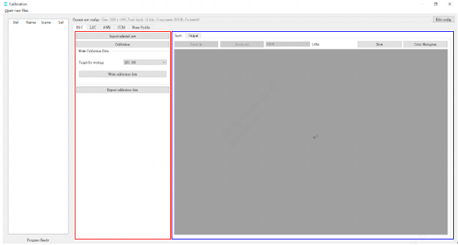
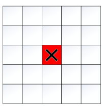
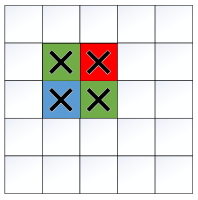
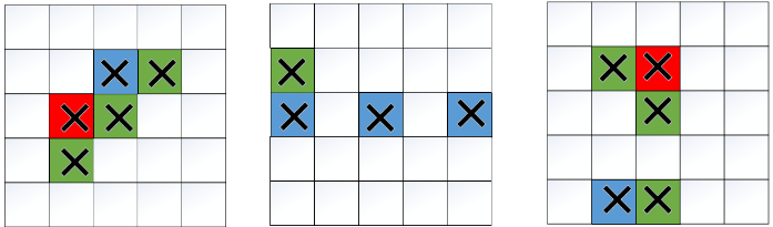
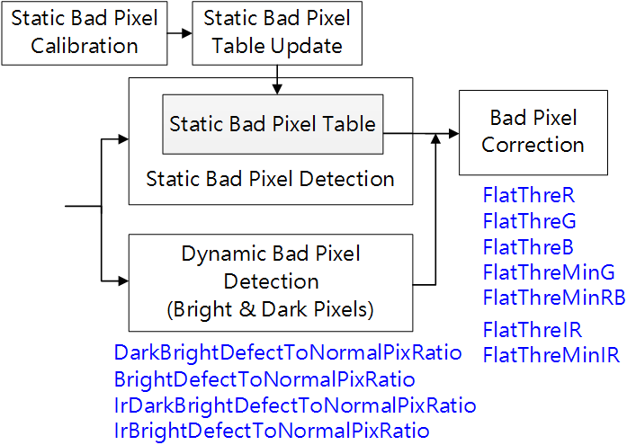
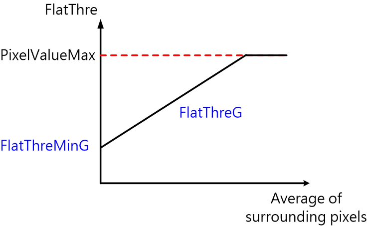
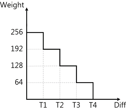
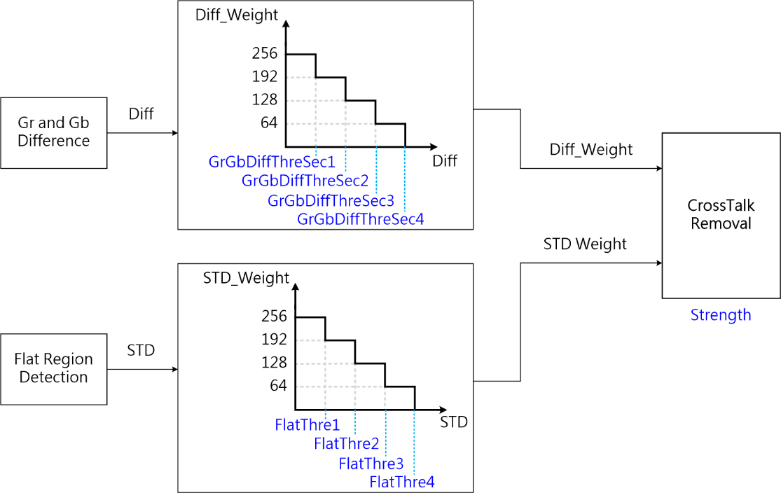
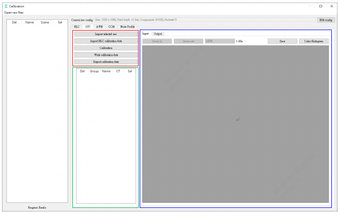

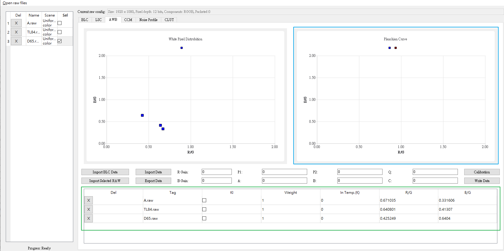

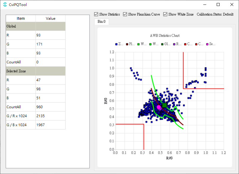
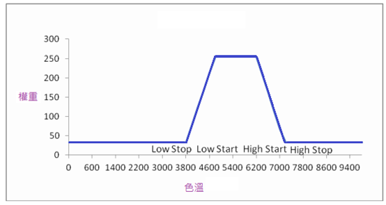

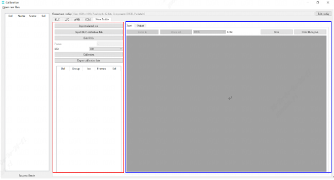
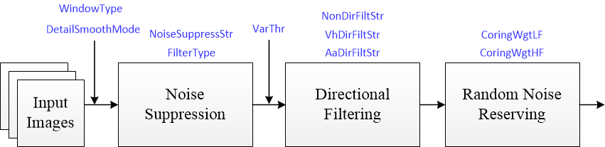
Tuning principle: as far as possible to maintain the uniformity of the overall image noise, and avoid impact noise, worm noise and pattern noise. For the configuration of parameters WindowType and DetailSmoothMode, it is recommended to use the default value first.
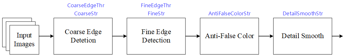
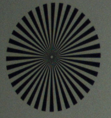
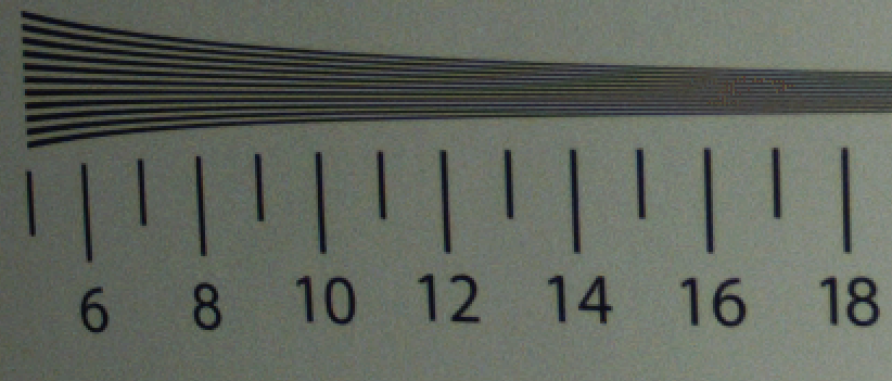
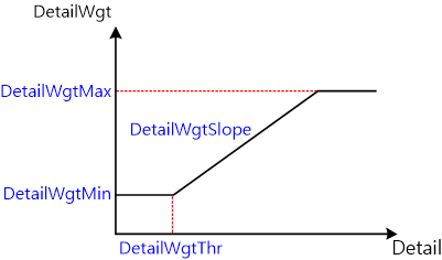
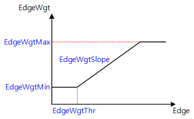
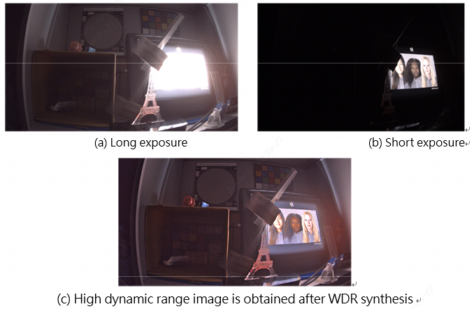
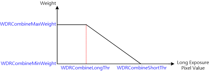
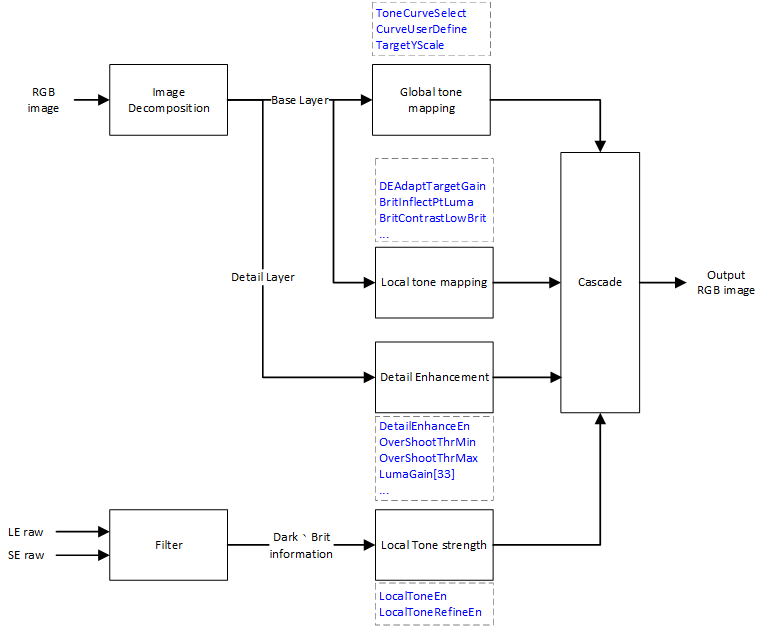
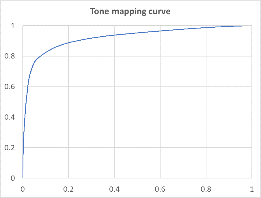
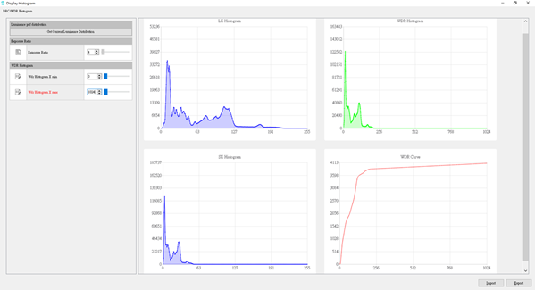
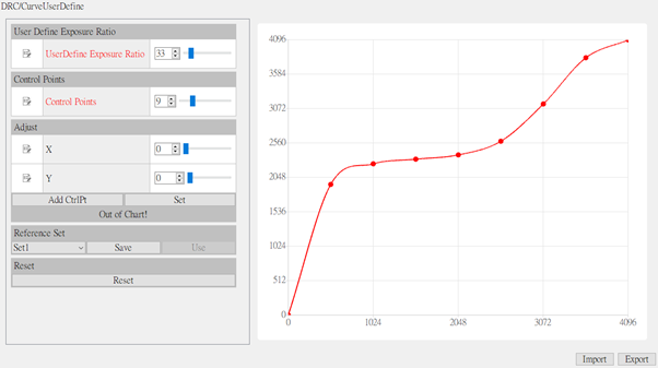
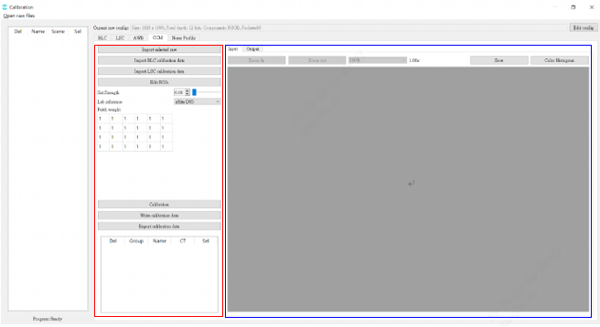
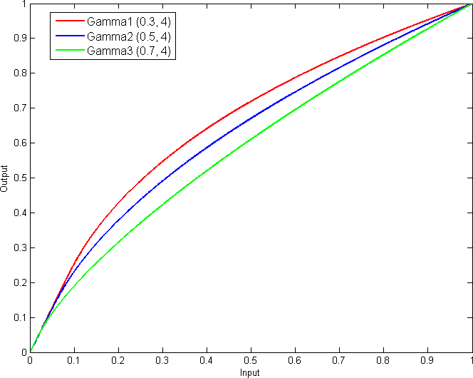
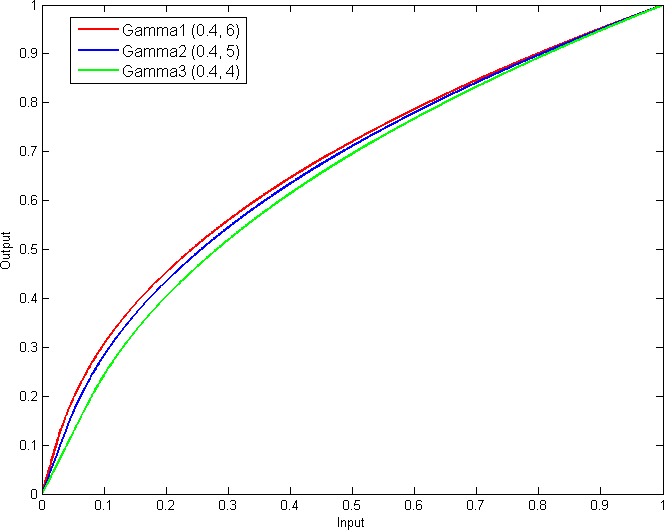
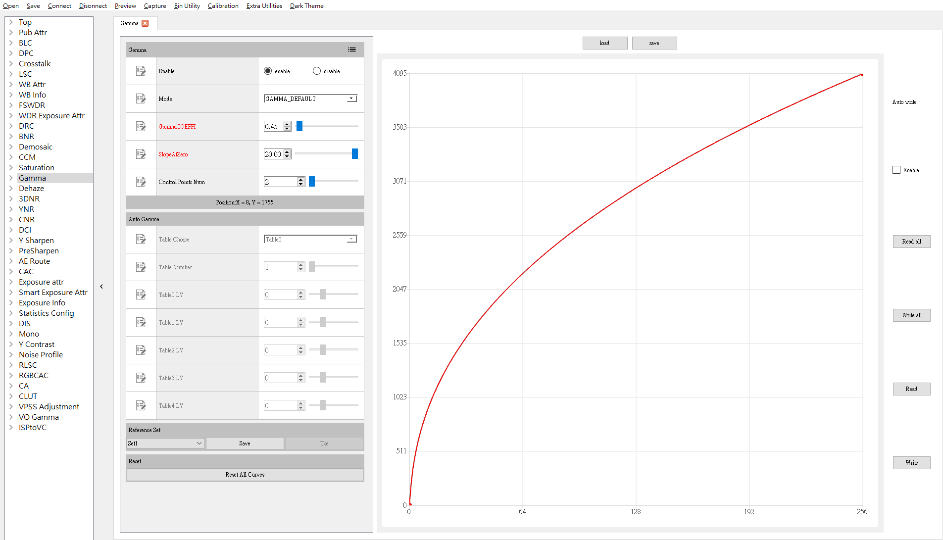
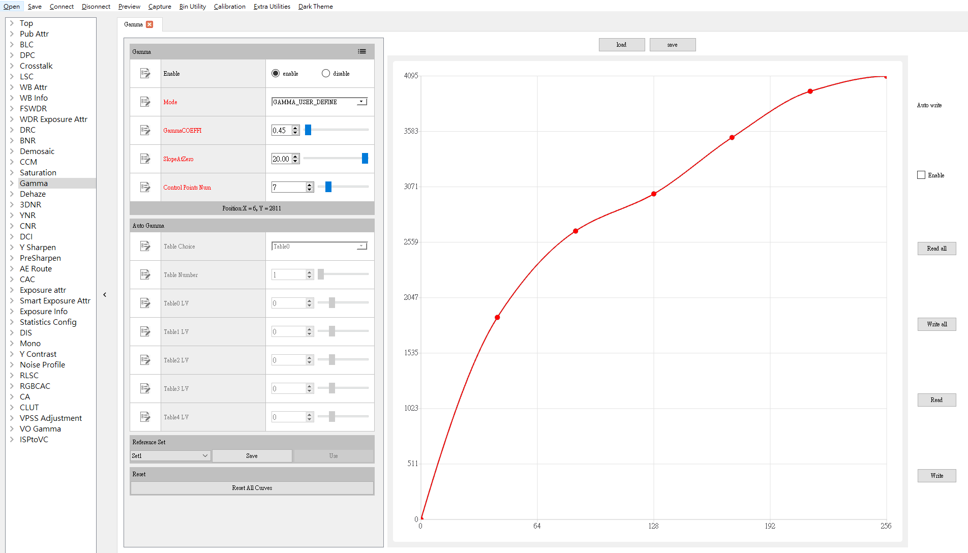
Description
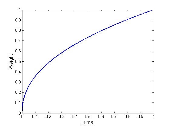
Tuning principle: Default values are recommended for PurpleCb/PurpleCb2/PurpleCb3, PurpleCr/PurpleCr2/PurpleCr3, GreenCb and GreenCr. Interested users only need to fine tune the default values for PurpleCb/PurpleCb2/PurpleCb3, PurpleCr/PurpleCr2/PurpleCr3.