10.2. Design Overview
10.2.1. System Architecture
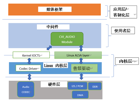
Fig. 10.1 Figure9-1
Please refer to 9.1.2.
The audio module mentioned in this article (audio input module, audio output module, audio encoding module, audio decoding module, audio quality enhancement module, resampler) is one of the Middleware multimedia layer interfaces that interconnect with application layer or customer business layer apis.
Users can control corresponding audio components through functions (CVI_AI, CVI_AO, CVI_ADEC, CVI_AENC_related prefix beginning, etc.).
The Application Layer or customer business layer is called Application/Customize Layer.
Refer to 9.3: API Reference in this document for details.
If you need the related API call logic, refer to the example in cvi_sample_audio.c in the SDK to understand the use sequence among basic audio modules (the following figure).
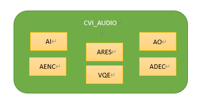
Fig. 10.2 Figure9-2
VI_AUDIO interfaces with Linux kernel layer related driver programs through the Linux standard sound system (ALSA: Advanced Linux Sound Architecture), which enables basic audio input and output functions.
Therefore, it can be understood that when a user calls the cvi_audio_xxx/ cvi_axx_xx (e.g. cvi_adec_xxx) API, the internal basic and minimum audio unit is a Frame (referred to as an Audio Frame in this document), and the unit of measurement for frames in this document is the number of samples in a frame, rather than bits (bytes).
The size range of a Frame, without using the Voice Quality Enhancement (VQE) module, can be set to 160/320/480 samples as the frame size (not to exceed 512).
When using VQE, the frame size must be set to a multiple of 160 samples, which is designed to be compatible with the internal VQE module.
For users, in addition to the Audio Codec function or related debugging requirements, the basic functions are realized through the libcvi_audio, libcvi_xxx related so file, and will not directly call the IOCTL function control kernel layer, to ensure the stability and reliability of the system internal resource allocation.

Fig. 10.3 Figure9-3
The figure above depicts the relationship between audio input and encoding.
AENC uses RISC-V encoding to store the stream in DDR without passing through the core layer, and enables the stream sequentially from the radio end (supporting microphone radio and voice line radio) to the encoding end.
When Audio Input and AENC modules are enabled, the internal API parameters (sampling rate, sound frame size, and number of channels) must be set as consistent as possible;
otherwise, the audio obtained after encoding is abnormal.
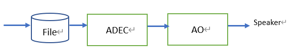
Fig. 10.4 Figure9-4
The figure above describes the relationship between audio decoding and output.
Users can directly put the pcm/raw audio file into the storage device and call ADEC/Audio Output API for broadcasting, and enable it in sequence from the decoding end to the output end.
ADEC and Audio Output parameters should be set as consistent as possible, otherwise the audio will be abnormal.
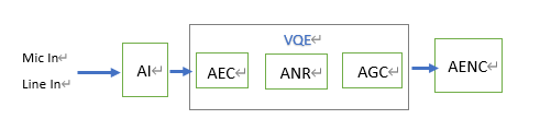
Fig. 10.5 Figure9-5
The figure above illustrates the relationship before and after the VQE.
After the audio is received and before the encoding, the user can enable the AEC/ANR/AGC function through the VQe-related API(see 9-3).
At this time, the unit of the sound frame needs to be set as a multiple of 160 and the operating frequency can be 8Khz/16Khz.

Fig. 10.6 Figure9-6
VQE includes the front-end VQE (Figure 9-5) and the broadcasting VQE (back-end VQE) described in the figure above.
Currently, back-end VQE is not supported.
10.2.2. Audio Input and Output
10.2.2.1. Audio Interface and Audio Input/Output Device
Audio interface is divided into two types, input (Audio Input) and output (Audio Output) interface, each responsible for recording and playing sound.
The unit that connects with Audio Codec and is responsible for the input function of abstract audio interface is called Audio Input device; Audio Output device is responsible for the output function of abstract audio interface.
According to the functions supported by the interface, it establishes mapping with Audio Input device and Audio Output device respectively.
Audio input / output interface is called AIO (Audio Input / Output) interface for docking with Audio Codec to complete sound recording and playback. AIO interface can be divided into two types: input only or output only.
When it is an input type, it is also called AIP; when it is an output type, it is also called AOP.
If Audio Input P0 only supports audio signal input, Audio Input P0 image is AiDev0; if Audio Output P0 only supports audio signal output, Audio Output P0 image is AoDev0.
The audio input interface (Audio Input) supports PCM and I2S input, and the output is connected with ALSA PCM device according to the Linux kernel Standard Specification.
Cvitek supports a set of preset input and output.
If viewed from the Linux ALSA architecture, the corresponding devices can be regarded as card 0 and card 1, and the relationship is as follows:
IP0 can only support input, Audio Output P0 can only support audio output.
In the case of input and output docking, such as real-time recording and dialing or voice intercom, the sampling rate and bit width of Audio Input / AO equipment must be the same, the number of channels must be the same, and the sampling rate must be the same.
In order to meet the needs of customized products, Cvitek has two more sets of I2S, which can be changed to AiDev (input) pair interface or AoDev (output) pair interface according to the needs of products or customer applications.
10.2.2.2. Principle of Recording and Playing
The audio frames processed by the CVI_AUDIO API are all digital signals. However, in fact, they are analog signals at both the radio and the broadcasting terminals. The digital and analog signals are converted through the Audio Codec. The Audio Codec converts the input analog signal source through I2S or PCM timing and transmits it to the Audio Input module. Similarly, the Audio Output terminal broadcasts through the Audio Codec will do DAC conversion of digital audio with I2S or PCM timing, and then send simulation signal to speaker.
The data transfer is controlled by RISC-V in DMA mobile memory DDR. When users call CVI_AUDIO API, they only call Audio Codec at the beginning or end, so as to realize the initial and standard end of Audio Codec hardware standard. During the process, it does not involve the capture of simulation signal, nor can it directly change the RISC-V using DMA mode. Audio Codec is the translator of the working domain, while RISC-V/DMA is the role of data movers. (see Figure 9-7 below)
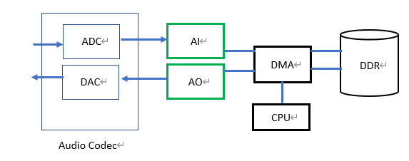
Fig. 10.7 Figure9-7
10.2.2.3. Audio Interface Timing
Cvitek audio timing interface supports I2S, PCM timing mode, and provides a variety of ways to interface with Audio Codec according to customization.
Please refer to hardware related documents for detailed processor hardware specifications.
Audio Input / Audio Output controls the clock to synchronize the timing.
Users can refer to cvi_sample_comm_audio.c’s internal SAMPLE_COMM_AUDIO_Cfg Acodec API.
The timing setting method of built-in Audio Codec or external Audio Codec will be different.
However, for cvi_audio API users, they only need to confirm that the kernel can support and initialize Codec at the time of initial Audio Codec.
For the frame sampling rate, Cvitek uses RISC-V software to sample, which is not directly related to the master clock.
When Audio Input equipment uses multiplexed I2S receiving mode, the standard I2S protocol only has the concept of left and right channels.
Audio Input equipment can receive 128bit audio data from left and right channels at most.
Please refer to section 9.4.4 for details of Codec.
10.2.2.4. Resample
Voice frame resampling supports conversion of any two different sampling rates, mainly 8kHz frequency doubling.
The input sampling rates supported by resampling are: 8kHz, 11.025kHz, 16kHz, 22.05kHz, 24kHz, 32kHz, 44.1kHz, 48kHz;
the output sampling rates supported are: 8kHz, 11.025kHz, 16kHz, 22.05kHz, 24kHz, 32kHz, 44.1kHz, 48khz.
Users should note that Resampling supports processing mono and stereo audio.
Audio Input resampling, the resampling input sampling rate and Audio Input device property configuration sampling rate are the same, the resampling output sampling rate must be different from Audio Input device property configuration sampling rate;
Audio Output resampling, resampling output sampling rate and Audio Output device property configuration sampling rate are the same, resampling input sampling rate must be different from Audio Output device property configuration
Audio Input-Audio Output data is transmitted by system bind, and resampling of Audio Input or Audio Output is invalid.
Users with Audio Input resampling enabled in user-get mode can use CVI_AI_GetFrame gets the data and gets the corresponding resampled data.
If Audio Output is enabled for resampling, audio data needs to be resampled before being sent to AO, and then sent to Audio Output channel (CVI_AO_SendFrame) to play.
Related API:
CVI_Resampler_Create: Create and initialize audio resample.
CVI_Resampler_GetMaxOutputNum: Based on the number of sample points entered, the corresponding number of resampled points is obtained.
CVI_Resampler_Process: Through this API, the sample number of audio frames is continuously passed in for actual resampling.
CVI_Resampler_Destroy: Finish the resampling process.
10.2.2.5. Voice Quality Enhancement (VQE)
For the speech signal processing algorithm, when the near end speech signal is interfered by the echo from the far end or the near end stationary noise, the algorithm function in VQE can be used to improve the quality of the speech signal.
VQE provides four solutions, including linear echo cancellation (AEC), nonlinear echo suppression (AES), speech noise reduction (NR) and automatic gain control (AGC).
The algorithm can support 8kHz and 16kHz sampling rate, mono and 16bit sampling length.
The following pages will introduce each function and the parameters used.
For a more detailed understanding, please refer to the Audio Quality Tuning Guide.
Parameter para_fun_config can control the function of AEC、AES、NR and AGC.
The para_spk_fun_config parameter controls the speaker path SSP algorithm function and belongs to UpVQE.
The following table shows the algorithm functions corresponding to each bit.
para_fun_config |
Description |
|---|---|
bit0: |
0: turn offAEC 1: turn onAEC |
bit1: |
0: turn offAES 1: turn onAES |
bit2: |
0: turn offNR 1: turn onNR |
bit3: |
0: turn offAGC 1: turn onAGC |
bit4: |
0: turn off Notch Filter 1:turn on Notch Filter |
bit5: |
0: turn offDC Filter 1: turn on DC Filter |
bit6: |
0: turn off DG 1: turn on DG |
bit7: |
0: turn off Delay 1: turn on Delay |
para_spk_fun_config |
Description |
|---|---|
bit0: |
0: turn off AGC 1: turn on AGC |
bit1: |
0: turn off EQ 1: turn on EQ |
Aiming at the similarities and differences between Audio Input and Ao, VQE processes the data of the two channels through UpVQE and DnVQE scheduling logic respectively.
UpVQE includes AEC, AES, NR and AGC.
DnVQE is currently not supported.
The corresponding parameters can refer to the header file cvi_comm_aio.h。
AGC data structure is as follows:
CVI_S8 para_agc_max_gain;
CVI_S8 para_agc_target_high;
CVI_S8 para_agc_target_low;
CVI_BOOL para_agc_vad_ena;;
NR data structure is as follows :
CVI_U16 para_nr_snr_coeff;
CVI_U16 para_nr_init_sile_time;
The AI_TALKVQE_CONFIG_S *pstVqeConfig parameter in the CVI_AI_SetTalkVqeAttr, sets u32OpenMask to decide which function of VQE to turn on.
For a more detailed Description of AGC and NR members, please refer to the corresponding sub-sections below.
Examples are shown in the table below:
pstAiVqeAttr.u32OpenMask |
Description |
|---|---|
pstAiVqeAttr.u32OpenMask =AI_TALKVQE_MASK_AGC; |
turn on AGC |
pstAiVqeAttr.u32OpenMask =AI_TALKVQE_MASK_ANR; |
turn on NR |
pstAiVqeAttr.u32OpenMask =(AI_TALKVQE_MASK_ANR AI_TALKVQE_MASK_AGC); |
turn on NR, turn on AGC |
AEC/AES (Acoustic Echo Cancellation/Acoustic Echo Suppression)
There is echo interference in the architecture of any duplex communication system.
The echo canceller can eliminate the echo from the speaker output coupled back to the microphone through the near end acoustic path.
The linear adaptive filter module (AEC) combined with the nonlinear echo suppression module (AES) can effectively suppress the echo and improve the quality of voice calls.
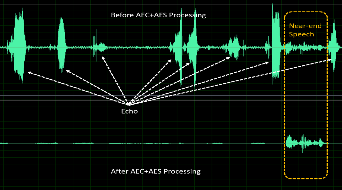
Fig. 10.8 Figure 9-1: Performance before and after AEC + AES treatment
Three adjustable parameters are provided to adjust the performance of AEC / AES:
para_aec_filter_len:
The length of the adaptive filter.
Adjust the length of filter according to the time of echo tailing.
Choosing a longer length will lead to higher MIPS and power consumption.
para_aes_std_thrd:
The threshold of residual echo was determined.
When the value is larger, the near end speech quality is better, but the residual echo is more.
On the contrary, when the value is small, the near end voice quality is poor, but the residual echo is less.
para_aes_supp_coeff:
Residual echo suppression.
The larger the value is, the stronger the residual echo suppression will be, but at the same time, more details will be lost / damaged in the near end speech.
AEC/AES parameter |
Ad justable range |
Description |
|---|---|---|
para_aec_filter_len |
1 - 13 |
8kHz sampling rate: [1,13] corresponding to [20ms,260ms] 16kHz sampling rate: [1,13]corresponding to [10ms,130ms] |
para_aes_std_thrd |
0 - 39 |
0: minimum threshold of residual echo 39: maximum threshold of residual echo |
para_aes_supp_coeff |
0 - 100 |
0: Minimal residual echo suppression 100: Maximum residual echo suppression |
NR (Noise Reduction)
The NR module can suppress the surrounding steady noise, such as fan noise, air conditioning noise, engine noise, white / pink noise.
With the proprietary voice intelligent Voice Activity Detection (VAD) algorithm, NR can maintain the voice signal and effectively suppress the steady noise, so as to improve the quality of voice calls.
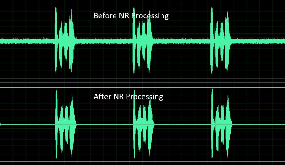
Fig. 10.9 figure 9-2: The performance before and after NR treatment
Three adjustable parameters are provided to adjust the performance of NR:
para_nr_init_sile_time:
Initial duration of silence.
CODEC will generate random meaningless noise signal when turned on, so it is recommended to set an initial duration of silence to avoid this.
para_nr_init_sile_time:
You can set this signal to mute.
para_nr_snr_coeff:
Prior Signal to Noise Ratio (SNR) tracking coefficient.
If the parameter value is larger, NR will have higher noise reduction ability, but the speech signal may be more easily distorted.
On the contrary, if the parameter value is small, NR will suppress less noise signal, but it will have better speech quality performance.
The following table is based on the appropriate adjustment range of this parameter in different SNR environments.
In each SNR case, the larger the parameter value is, the greater the suppression force to stationary noise is.
NR parameter |
Adjusting range |
Description |
|---|---|---|
para_nr_init_sile_time |
0-250 |
Corresponding to 0s to 5s, with a step of 20ms. |
Surrounding SNRenvironment |
Adjusting range |
Description |
|---|---|---|
low |
0 - 3 |
0: The least active in noise reduction 3: The most active in noise reduction |
medium |
4 - 10 |
4: The least active in noise reduction 10: The most active in noise reduction |
high |
11 - 20 |
11: The least active in noise reduction 20: The most active in noise reduction |
AGC (Automatic Gain Control)
AGC module is a signal processing function, which can automatically adjust the output level to a predetermined range to provide a more comfortable hearing experience.
If the input signal is lower than “Target Low”, AGC will adjust the output level to “Target Low”.
On the other hand, if the input signal is higher than “Target High”, AGC will adjust the output level to “Target High”.

Fig. 10.10 Figure9-3: AGC adjusts signal level
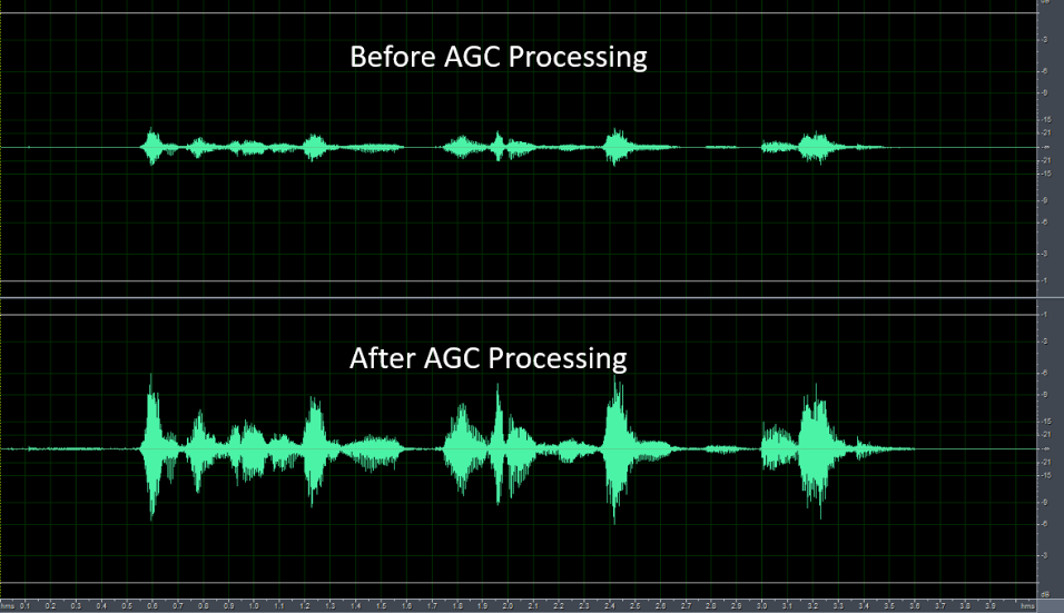
Fig. 10.11 Figure9-4: Performance before and after AGC treatment
Four adjustable parameters are provided to adjust the performance of AGC
para_agc_max_gain:
This parameter is the maximum gain that the signal can be amplified.
para_agc_target_high:
This parameter is the “Target High” level AGC will reach.
For the input signal higher than para_age_target_high, AGC will converge it to para_age_target_high.
para_agc_target_low:
This parameter is the “Target Low” level AGC will reach.
For the input signal lower than para_age_target_low, AGC will converge it to para_age_target_low.
If para_age_max_gain is reached before para_age_target_low, AGC will only converge to para_age_max_gain.
para_agc_vad_ena:
Speech-activated AGC function.
When this function is turned on and NR and AEC / AES functions are turned on at the same time, AGC can avoid amplifying background stable noise and residual echo, so as to obtain better effect.
AGC parameter |
A djustable range |
Description |
|---|---|---|
para_agc_max_gain |
0 - 6 |
The maximum lifting gain corresponding to [0,6] is [6dB, 42db], and each order is 6dB |
para_agc_target_high |
0 - 36 |
0 to 36 corresponds to 0dB to - 36dB |
para_agc_target_low |
0 - 36 |
0 to 36 corresponds to 0dB to - 36dB |
para_agc_vad_ena |
0 - 1 |
0: turn offSpeech-activated AGC function 1: turn onSpeech-activated AGC function |
10.2.3. Audio Enoding and Decoding
10.2.3.1. Audio Codec Process
Cvitek audio codec supports G711-A-law, G711-Mu-law, G726, and ADPCM_IMA, the above codec uses RISC-V software codec.
Users can use bind mode and use CVI_Aud_SYS_Bind, bind Audio Input to AENC to encode the voice frame, or bind Audio Output to ADEC to decode the received encoded voice frame to restore the voice frame to PCM / Raw signal.
If user get mode is used instead of bind mode, users can use CVI_AENC_SendFrame sends the actual single sound frame into the encoding program for encoding, and CVI _ADEC_GetFrame can also be used correspondingly to decode a single audio frame.
Please note that when using user access mode, if the user’s call delay is too long, the internal cache may be blocked and the failed audio frame will be returned.
10.2.3.2. Audio Codec Protocol
CodecProtocol (coding) |
Bit Rate (Bit RateKbps) |
Playload ( Suggest original sound frame) |
Compress Rate (compress rate) |
MOS ( Sound quality me asurement) |
|---|---|---|---|---|
G711 |
64 |
160/320 |
1:2 |
4.1 |
G726 |
16、24、32、40 |
160/320/480 |
1:4 |
3.85 |
ADPCM-IMA |
32 |
160/320/480 |
1:4 |
3.7 |
10.2.3.3. Speech Frame Structure
Cvitek and audio frame structure do not have additional header files.
Internal radio and broadcast are based on audio frame, and each audio frame is RAW / PCM data.
For encoding and decoding in G711, G726 and ADPCM formats, the corresponding audio frame will not add extra header.
Users must pass through CVI_AUDIO_AENC/CVI_AUDIO_ADEC
Related API to get the current codec voice box information.
The advantage of this method is that when the user obtains the sound frame through the get_frame API or the related debug function, he can immediately identify whether the sound frame conforms to the corresponding encoding and decoding rules, without having to parse the header, and can verify whether the encoding and decoding results are normal with the relevant third-party software on the computer after saving.
10.2.4. Built-in Codec
10.2.4.1. Overview
Cvitek Audio Input P0 / Audio Output P0 interface can be connected with built-in audio codec or plug-in audio codec to record and play sound.
Users need to configure the timing and parameters of Audio Input P0 / Audio Output P0 and built-in audio codec to receive or send audio data.
In addition, the built-in audio codec only supports I2S mode.
The ADC codec needs to be configured as the master mode, and the DAC codec needs to be configured as the slave mode.
The built-in audio codec is divided into analog and digital parts.
The analog part can be input by microphone or by LINEIN and support gain adjustment.
The digital part has ADC and DAC, which are mainly responsible for the conversion between analog and digital signals.
ADC can adjust the left and right channel volume respectively, while DAC can’t adjust the left and right channel volume separately.
In addition, it supports mute and unmute.
When unmute is cancelled, it will return to the gain value configured before mute.
The MCLK with built-in audio code is provided by CV182X.
The default sampling precision is 16 bit and the sampling frequency is 16Khz.
10.2.4.2. ioctl Function
The user interface with built-in Audio Codec is embodied in the form of IOCTL, which is as follows:
CVI_S32 ioctl (CVI_S32 fd, CVI_UL cmd);
This function is a standard interface of Linux and has variable parameters.
But in Audio Codec, only three parameters are needed.
Therefore, its grammatical form is equivalent to:
CVI_S32 ioctl (CVI_S32 fd, CVI_UL cmd, CMD_DATA_TYPE *cmddata);
Among them, CMD_DATA_TYPE changes with the change of parameter cmd.
The detailed description of these three parameters is shown in the table below:
Parameter |
Description |
Input/Ouput |
|---|---|---|
fd |
The built-in audio codec device file descriptor is the return value after calling the open function to open the built-in audio codec device file. ADC and DAC need to be configured separately. |
Input |
cmd |
Main cmd is as follows:
|
Input |
cmddata |
Data pointer corresponding to each cmd |
Input |