6.2. Design Overview
6.2.1. System Architecture
The following are the basic concepts of VPSS.
GROUP
VPSS provides the concept of GROUP for users.
VPSS_MAX_GRP_NUM for indicates the maximum number of GROUP.
Each group time-multiplexes the VPSS hardware, which sequentially processes tasks submitted by each group.
CHANNEL
Channel of VPSS group.
VPSS hardware provides multiple physical channels, and each channel has the functions such as scaling and clipping.
It binds to a physical channel and takes the physical channel output as its input, scaling the image to the user-set target resolution and outputting it.
CROP
There are two kinds of clipping: Group clipping and physical channel clipping.
Group clipping. The VPSS crops the input image.
Physical channel clipping. The output image of each physical channel is cropped by VPSS.
Pixel format conversion
Support input and output image data format conversion.
Support mutual conversion of YUV420 planar, YUV422 planar, RGB planar, RGB packed and BGR packed
Scale
Zoom in and out of an image.
Physical channel supports at least 32 times smaller and at most 32 times larger horizontally and vertically.
Mirror/Flip
Mirror is the horizontal mirror; Flip means upside down. A 180-degree rotation can be achieved using Mirror + Flip.
Overlay/Overlayex
Video overlay area.
Call RGN to overlay bitmap on output image of VPSS channel.
It supports bitmap format such as ARGB4444, ARGB1555, ARGB8888, 256 LUT(ARGB4444), and Font-based.
Fixed angle rotation
Call GDC to process the output image of VPSS channel.
It supports 0 degrees, 90 degrees, 180 degrees and 270 degrees fixed angle rotation.
The location of Vpss module in the system is shown in the figure below.
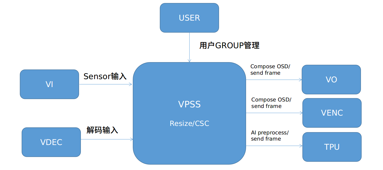
By calling the binding interface provided by the SYS module, the VPSS module can be bound to input modules such as VI/VDEC to process decoding and sensor data through VPSS, enabling functions such as image scaling and color space conversion.
At the same time, through the binding interface, the images processed by the VPSS module can be synthesized by OSD and sent to the VO / VENC module.
It also supports some simple Deep Learning pre-processing, and then the processed images can be sent to the TPU for Deep Learning computation.
Table 6 - 1
Working Mode |
Function |
||
|---|---|---|---|
Group clipping |
Zoom |
Channel clipping |
|
VI_OFFLINE_VPSS_OFFLINE |
support |
support |
support |
VI_OFFLINE_VPSS_ONLINE |
Not support |
support |
support |
VI_ONLINE_VPSS_OFFLINE |
support |
support |
support |
VI_ONLINE_VPSS_ONLINE |
Not support |
support |
support |
Note
When VPSS is ONLINE, it can only receive data from two front-end sensors through two groups, and cannot serve other different sources.
6.2.2. Note
The data processing flow chart of VPSS is shown in Figure 6-1 below.
There are two groups of input.
When a single input is used, there can be four groups of channel outputs (CV180x is three groups);
When two groups of input are used, the first group of input has only one group of channel for output, and the second group of input has only three groups of channels for output (CV180x is two groups).
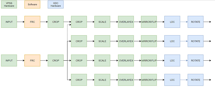
Fig. 6.1 Figure 6- 1 Data flow chart of CV181x
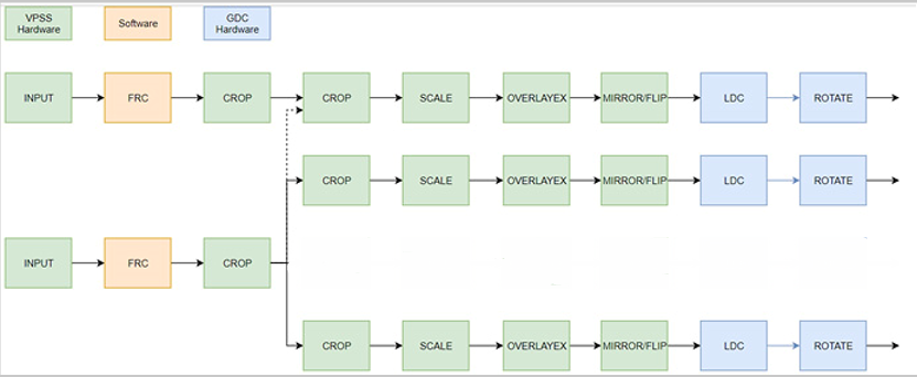
Fig. 6.2 Figure 6- 2 Data flow chart of CV180x
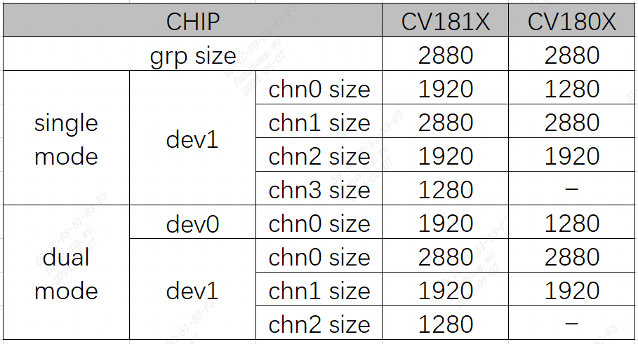
Fig. 6.3 Figure 6- 3 Hardware Limitation of CV180x_CV181x