2. Preface
2.1. Overview
This document mainly introduces the user interface of ISP.
It can be divided into system control, 3A and ISP modules.
The first part is system control, which explains how to control ISP middleware.
The second part is 3A, which explains how to control AE, AWB and AF.
Most of the functions in this area can be debuged in CVI PqTool.
The third part is the ISP modules, which explains how to control the black level cancellation, color correction matrix, gamma, noise reduction, sharpness and other modules.
Most of the functions in this area can be debuged in CVI PqTool.
2.2. Function Overview
The control structure of ISP is shown in Fig. 2.1 .
Lens - project focused light signal to the sensitive area of sensor
sensor - after photoelectric conversion, the original image in Bayer format is sent to ISP
ISP –in this process, ISP controls ISP logic, lens and sensor through firmware running on it, so as to complete automatic aperture, automatic exposure, automatic white balance and other functions. Among them, the operation of firmware is driven by the interrupt of video capture unit. PQ tools can adjust ISP’s online image quality through network port or serial port. Output YUV domain image to the back-end video capture unit.
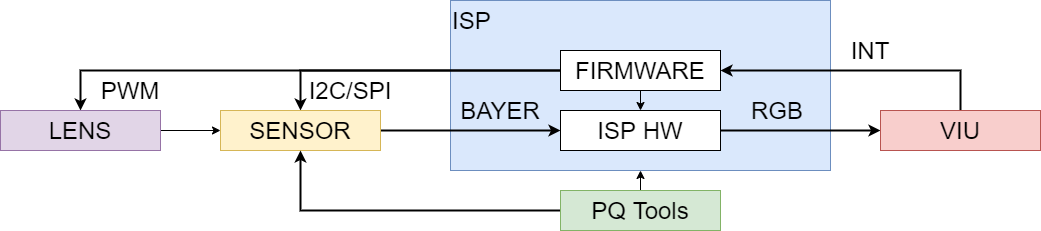
Fig. 2.1 ISP Control structure diagram
Please refer to the processor manual for ISP logic main process, specific concepts and function points.
2.3. Architecture
ISP firmware can be divided into three parts.
The first part is ISP control unit and basic algorithm library, the second part is 3A algorithm library, including AE and AWB, and the third part is the sensor library.
The software architecture is divided into three parts, and can evolve independently by registering function callbacks.
For example, developers can implement 3A functions by themselves.
As long as they implement the same interface and register, they can replace the default 3A Library of Cvi.
The ISP firmware architecture is shown in Fig. 2.2 .
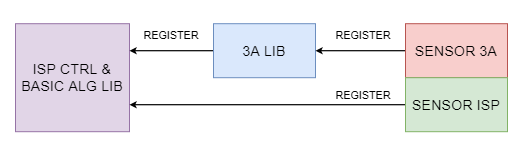
Fig. 2.2 ISP firmware Structure
Different sensors register control functions with ISP algorithm library in the form of callback functions.
When ISP control unit schedules basic algorithm library and 3A algorithm library, it will obtain initialization parameters through these callback functions and control sensor, such as adjusting analog gain, digital gain and exposure time.
2.4. Development Mode
SDK supports users to use multiple development modes.
Users use the 3A algorithm library of CVITEK.
At this time, users need to adapt different sensors according to the sensor adaptation interface given by ISP basic algorithm library and 3A algorithm library.
Each sensor corresponds to a folder, which contains two main files.
- sensor_cmos.c
This paper mainly implements the callback function needed by ISP, including the sensor adaptation algorithm. Different sensors may be different.
- sensor_ctrl.c
The underlying control driver of sensor mainly realizes the reading, writing and initialization of sensor.
In order to be compatible with multiple sensors at the same time, the above two file names will be added to the sensor model. For example, Sony imx307 will be named i imx307_cmos.c and imx307_ctrl.c.
Users can develop these two files according to the datasheet of sensor, and seek support from sensor manufacturer when necessary.
According to the 3A algorithm registration interface provided by ISP library, users can develop their own 3A algorithm library. At this time, users need to adapt different sensors according to the sensor adaptation interface given by ISP basic algorithm library and user 3A algorithm library. Users can use part of the CVITEK 3A algorithm library and part of their own 3A algorithm library. For example, AE uses CVITEK AE algorithm library libae.a, AWB uses its own libawb.a algorithm library.
2.5. Internal Process
The internal process of firmware is divided into two parts, as shown in Fig. 2.3 . The first part is the initialization task, which mainly completes the initialization of ISP control unit, ISP basic algorithm library and 3A algorithm library, including calling the callback of sensor to obtain the initialization parameters of sensor differentiation. The other part is the dynamic adjustment process. In this process, ISP control unit in firmware schedules ISP basic algorithm library and 3A algorithm library, calculates and controls in real time.
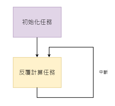
Fig. 2.3 ISP firmware Internal Process
The software structure of firmware is shown in Fig. 2.4 .
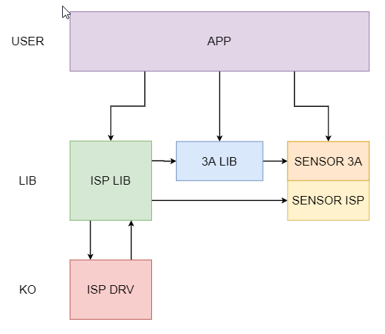
Fig. 2.4 ISP firmware Software Structure
2.6. Software Process
The software usage process is shown in Fig. 2.5 .
PQ Tools is mainly used to adjust the dynamic image quality on PC, which can adjust many factors that affect the image quality, such as denoising intensity, color conversion matrix, saturation and so on.
After debugging the image effect, users can save the configuration parameters by using the configuration file saving function provided by PQ tools. At the next startup, the system can use the configuration file loading function provided by PQ tools to load the adjusted image parameters.
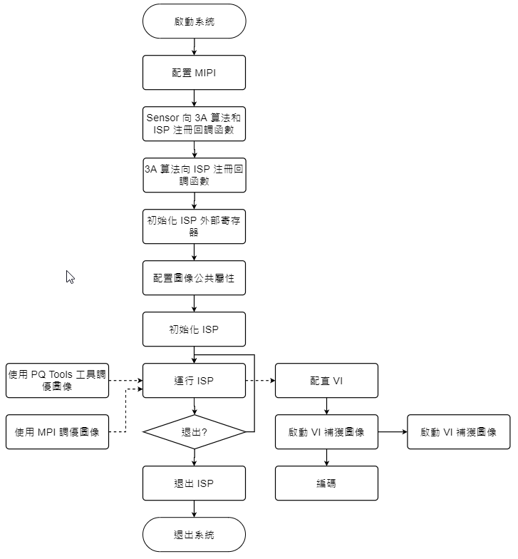
Fig. 2.5 ISP software usage process