10. AE Related Verification
After completing the image verification, AE handover work can be performed. AE handover needs to ensure that the basic exposure and gain are linear, and that issues such as response frame and synchronization are verified.
The main task is to perform the verification of the SensorPorting_AE (sensor_test) table. The verification work requires the use of a light box and the sensor_test testing program.
Note: When performing AE related verification, the previously commented-out code needs to be released.
Excel file: 
10.1. BLC Confirmation and Verification
The BLC offset value is usually specified in the sensor specification and can be directly written to xxx_cmos_param.h. If not specified, the actual BLC value can be obtained by the following method:
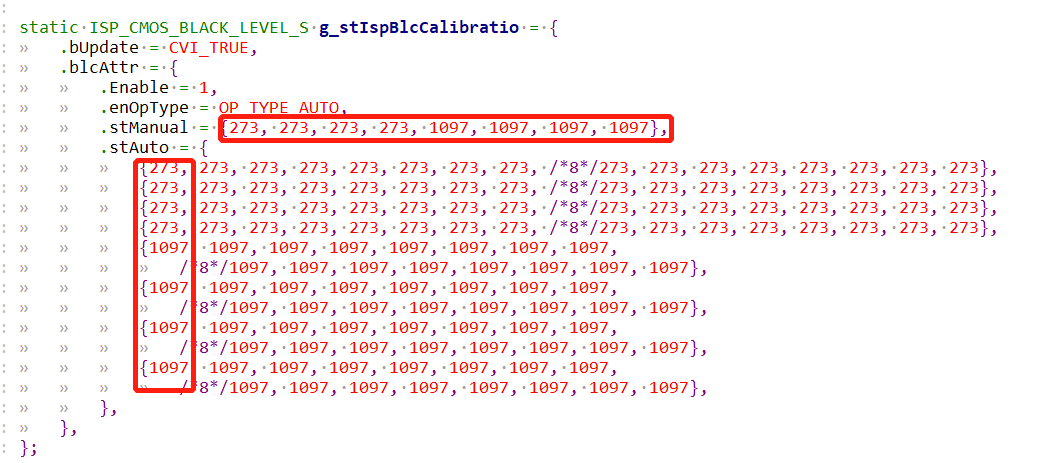
Modify xxx_cmos_param.h and change the values highlighted in red below: 273 represents the BLC offset and should be changed to 0, 1097 represents the gain and should be changed to 1024 for all instances.
Cover the lens and run sensor_test in a completely dark environment, then enter CMD.
5
2 0 70 0 0
Printing out the Luma value and multiplying it by 4 will give you the corresponding BLC offset value.
For example, the corresponding blc offset below is 74x4=286.
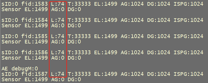
Finally, the tested blc offset was substituted into the formula gain = 4095 / (4095 - offset) * 1024 to obtain 1106, and the confirmed blc and gain were filled in xxx_cmos_param.h.
10.2. Exposure Linearity Verification
Point the camera at the light box and run sensor_test and Type CMD in linear mode.
5
2 0 71 0 0
Enter CMD for long exposure in Wdr mode.
5
2 0 75 0 0
Enter CMD for short exposure in Wdr mode.
5
2 0 76 0 0
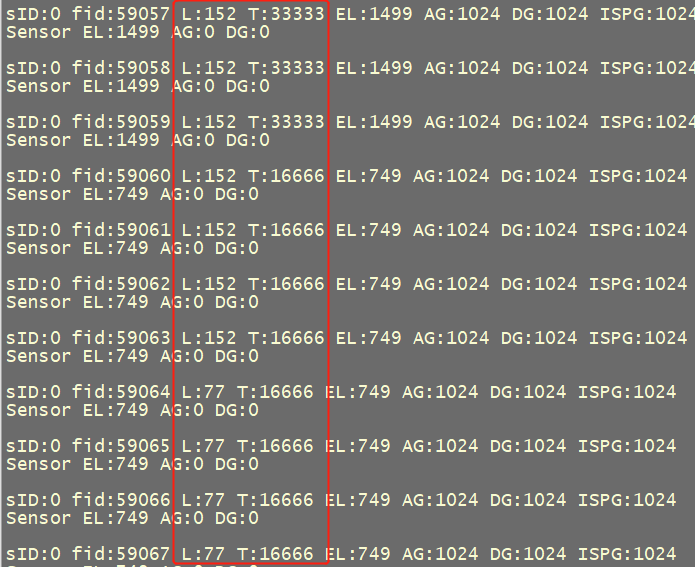
In order to satisfy the relationship that the exposure time of AE brightness statistics in 1/60s should be half of that in 1/30s, and the exposure time of AE brightness statistics in 1/120s should be half of that in 1/60s. For example, the results shown in the following figure are consistent.

10.3. Gain Linearity Verification
Point the camera at the light box and run sensor_test and type CMD in linear mode.
5
2 0 72 0 0
Enter CMD in Wdr mode.
5
2 0 77 0 0
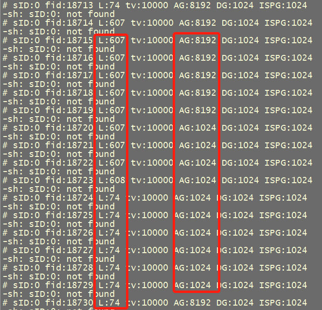
The following figure shows the test results. In linear mode, again the value increases from 1024 to 8192, and the luma value changes from 74 to 607, basically conforming to the eight-fold relationship. In Wdr mode, again changed from 1024 to 2048, and luma changed from 51 to 100, basically conforming to the two-fold relationship. So luma and again are linear.

10.4. Advanced Verification
If you want to verify exposure linearity exactly, you need to use CMD.
5
8 SID FID startExpTime endExptime
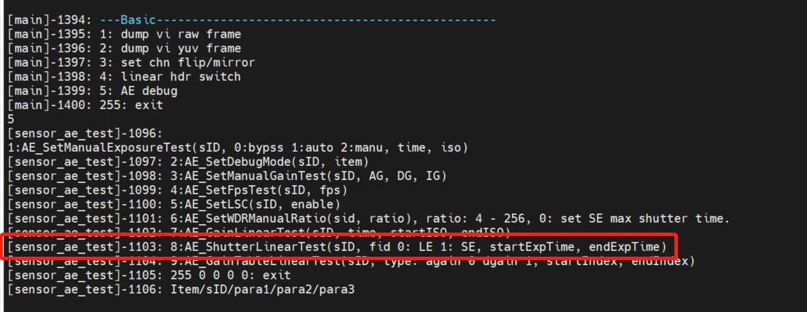
Continuous exposure linearity can be tested, representing precision increments of %5 from startExpTime to endExpTime.
SID represents sensorID, FID represents frameID, 0 represents long frame, and 1 represents short frame.
If you want to verify the gain linearity exactly, you need to use CMD.
5
7 SID FID time StartISO EndISO
You can test continuous gain linearity, representing increments as you traverse the gaintable from StartISO to EndISO. Here, ISO 100 indicates 1x, that is, gain = 1024.

10.5. Response Frame Verification
Different sensor parameters take effect at different times. For example, some sensors take effect after 5 frame, while others take effect after 4 frame or 3 frame. Even if the same sensor is set in different registers, the effective time may be different. Therefore, it is necessary to verify the reaction frame of the register related to AE.
Run sensor_test and enter CMD in linear mode.
5
2 0 71 0 0
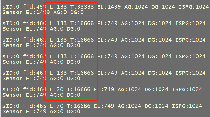
This measures how many frames have to pass before shutter is set to take effect. As you can see below, after shutter changes from 33333 to 16666, it takes 4 frames for the Luma value to change. So the exposed ResponseFrame is 4.
Enter CMD.
5
2 0 72 0 0
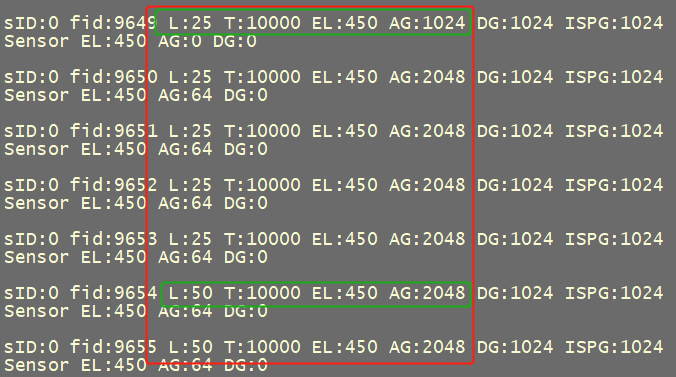
This measures how many frames elapsed after the gain is set before it takes effect. As you can see from the figure below, after changing again from 1024 to 2048, it takes 4 frames for the Luma value to change. So the ResponseFrame for the gain is 4.
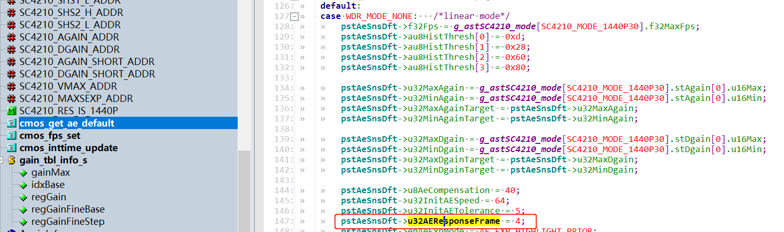
After the ResponseFrame of exposure and gain is tested, ResponseFrame is filled into the cmos_get_ae_default function of xxx_cmos.c, as shown below:
10.6. Validation of Exposure Gain Synchronization
Sometimes, not all sensors take effect with gain and shutter at the same time. For example, it may be possible that the ResponseFrame of gain is 4 and the ResponseFrame of shutter is 3, which requires verification by exposure gain synchronization mechanism.
Run sensor_test and enter CMD in linear mode.
5
2 0 73 0 0
This CMD indicates how long it takes for AE statistics to change while changing shutter/gain. In the figure below, you can see that changing shutter and again simultaneously takes effect after 4frames.
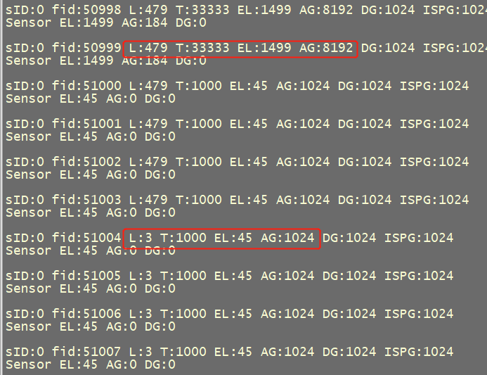
If the statistical value of AE changes after increasing gain and exposure at the same time, such as the following results, it indicates that gain and exposure do not take effect synchronously.
L:479 T:33333 AG:8192
L:479 T:33333 AG:8192
L:479 T:1000 AG:1024
L:479 T:1000 AG:1024
L:299 T:1000 AG:1024
L:211 T:1000 AG:1024
L:3 T:1000 AG:1024
L:3 T:1000 AG:1024
L:3 T:1000 AG:1024
L:3 T:1000 AG:1024
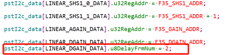
In this case, delay the gain or shutter to take effect. Modify the cmos_get_sns_regs_info function in xxx_cmos.c to change the delay setting of register.
For example, the following figure shows that the gain is delayed by 2 frames, indicating that it is 2 frames later than other register Settings.
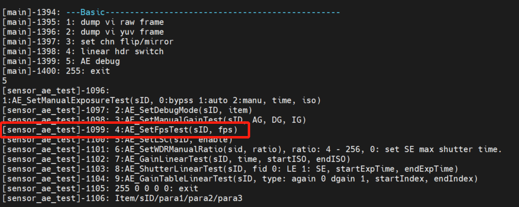
10.7. Verify FPS Controllability
Run with sensor_test and type CMD.
5
4 SID FPS
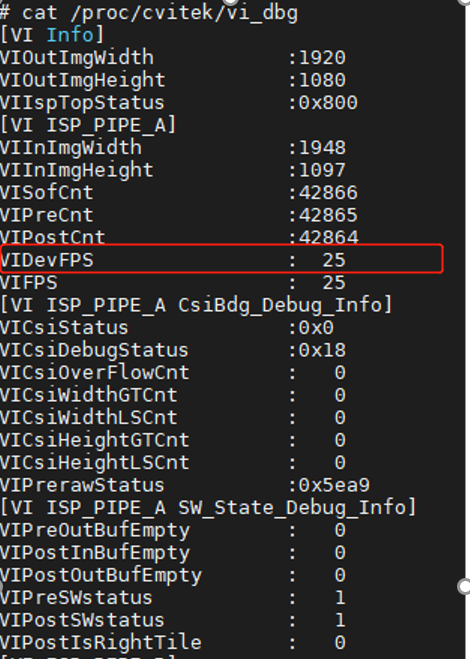
The default fps is 25fps. You can check the output fps of the sensor by cat /proc/cvitek-vi_dbg.