14. Debugging Tool
After developing the sensor, use the debugging tool “sensor_test” for testing.
The sensor configuration file is located at “/mnt/data/sensor_cfg.ini”.
Apply the patch “sensor_test.patch” in the middleware directory using the “git apply” command, and compile to generate “sensor_test” for use.
Patch file:
14.1. Basic Functions.
By default, sensor_test has the following 5 functions, as shown in the figure below:
Dump sensor raw image.
Dump sensor YUV image.
Set flip/mirror for the sensor output image.
If the sensor driver supports linear and WDR modes, this option can be used to switch sensor modes.
AE debugging function.

14.2. Dump RAW
Refer to 5.1 Dump RAW.
14.3. Dump YUV
Refer to 5.2 Dump YUV.
14.4. Set flip/mirror
It provides mirror/flip functionality.
Run sensor_test and enter 3 to select “set chn flip/mirror”. Follow the prompt chn(0 to 1): Enter dev (0 indicates vi pipe0 to control channel 0, 1 indicates vi pipe1) to switch on flip/mirror.
Note: After the function is executed, ensure that the direction and color of the dump yuv diagram are as expected.
14.5. Switching between WDR and Linear
It provides the switch function between sensor end width dynamic mode and linear mode.
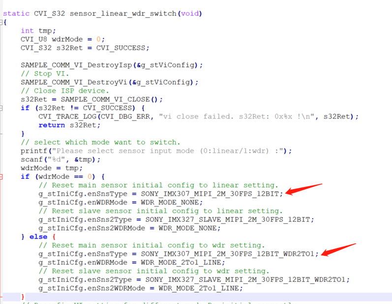
Run “sensor_test” and select option 4 “linear hdr switch”. Then, follow the prompt “Please select sensor input mode (0:linear/1:wdr) :” to enter 0 for Linear or 1 for WDR.
Note:
This function requires the sensor to support both Linear and WDR modes.
Different sensor configurations need to be modified in the “sensor_test.c” file, as shown in the figure below.