8. Complete the AE Configuration Function
The functionality of the sensor driver is implemented through operation callbacks. This section assumes that the user is familiar with the sensor datasheet and describes the basic functions that should be implemented by the AE callbacks.
8.1. Development Process
Please implement the following basic AE functional callbacks in order.
pfn_cmos_get_ae_default
pfn_cmos_fps_set
pfn_cmos_inttime_update
pfn_cmos_gains_update
pfn_cmos_again_calc_table
pfn_cmos_dgain_calc_table
pfn_cmos_get_inttime_max
8.2. Notes
pfn_cmos_get_ae_default - Returns sensor data related to AE algorithm.
It is required to provide the maximum and minimum number of exposure steps in linear mode of AE algorithm, the maximum and minimum values and types of gain in linear/WDR mode simulation/digital gain. If the digital gain only has a few choices such as 0dB, 6dB, 12dB, etc., it is a DB type, otherwise it is linear. Also, the number of frames in the exposure effective period, and the number of frames after the start-up which is stable.
u32FullLinesStd: Number of lines in one frame at initialization.
u32MaxAgain: Maximum AGain value.
u32MinAgain: Minimum AGain value.
u32MaxDgain: Maximum DGain value.
u32MinDgain: Minimum DGain value.
u32MaxIntTime: Maximum exposure value in linear mode.
u32MinIntTimeTarget: Minimum exposure value in linear mode.
u32AEResponseFrame: Maximum AE response time (unit: frame).
The main task is to fill in the relevant AE properties according to the sensor spec, including FullLinesStd, FullLinesMax, max/min/step values for IntTime, as well as max/min/step values for gain. It is important to confirm the AccuType for IntTime and gain:
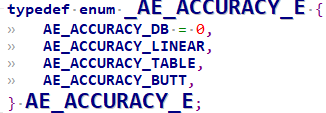
In general, the intTime setting is linearly related to the corresponding register, with AccuType set to AE_ACCURACY_LINEAR. The gain setting is usually set to AE_ACCURACY_TABLE, indicating mapping from the gain table, and we will introduce pfn_cmos_again_calc_table/pfn_cmos_dgain_calc_table later. However, some sensors may have special gain settings, such as the SOI_F35, which can only be adjusted in four steps: 1x, 2x, 3x, and 4x.
pfn_cmos_fps_set - Sets the frame rate of the sensor.
The default is the maximum frame rate of the Sensor output mode. The Sensor driver can reduce the frame rate by increasing the number of vertical blanking lines in the output. Note that changing the total number of output lines may also change the exposure range of some sensors, and the Sensor driver must recalculate it. For example, if the initial sequence has an FPS of 30, the new FPS cannot be greater than 30. The usual method of adjusting the frame rate is to increase the sensor output full lines in proportion. For example, if full lines = 1125 at FPS=30, the full lines at FPS=25 would be 1125*30/25 = 1350.
pfn_cmos_inttime_update - Sets the exposure time of the sensor and returns the actual number of exposure lines to the AE.
The input parameter is a sequence, which represents the exposure values of short and long exposure frames in order in WDR mode, in units of horizontal output lines. For example, when u32IntTime[0]=8 and u32IntTime[1]=1000, it means that the exposure time for the short exposure frame is 8 lines and for the long exposure frame is 1000 lines. If in linear mode, the value in sequence[0] represents the exposure value, and sequence[1] is meaningless. Note that in WDR mode, adjusting the exposure of the short frame of the sensor may require recalculation of the Crop information and MIPI-RX settings.
pfn_cmos_gains_update - Set the gain value for the sensor.
The input parameters are two arrays: pu32Again and pu32Dgain. In WDR mode, pu32Again[0] represents the analog gain value of the short exposure frame, pu32Again[1] represents the analog gain value of the long exposure frame; pu32Dgain[0] represents the digital gain value of the short exposure frame, and pu32Dgain[[1] represents the digital gain value of the long exposure frame. The values are the settings in the sensor buffer and can be converted to real gain values by pfn_cmos_again_calc_table and pfn_cmos_dgain_calc_table. In linear mode, only pu32Again[0] and pu32Dgain[0] are meaningful.
They can be converted to real gain values by pfn_cmos_again_calc_table and pfn_cmos_dgain_calc_table. In linear mode, only pu32Again[0] and pu32Dgain[0] are meaningful.
In WDR mode:
pu32Again[0]: Gain configuration for short frame.
pu32Again[1]: Gain configuration for long frame.
pu32Dgain[0]: Dgain configuration for short frame.
pu32Dgain[1]: Dgain configuration for long frame.
There are 3 modes for gains update - SHARE, WDR_2F, ONLY_LEF, which are set in pfnSetInit.
SHARE: Both short and long frames share the same gain configuration (Sony, OV).
WDR_2F: Short and long frames have separate gain configurations (Sony, OV).
ONLY_LEF: Only the gain for long exposure frame can be configured (SOI).
pfn_cmos_again_calc_table - Input is the analog gain value based on a reference of 1024. The sensor driver searches a lookup table or calculates the analog gain value that is closest and not greater than the input value, and outputs the corresponding sensor buffer setting.
pu32AgainLin: AE passes in the 1024-based Again value. The Sensor driver calculates the closest 1024-based Again value based on the gain table or formula specified in the datasheet and returns it. The range of Again is defined in pfn_cmos_get_ae_default.
pu32AgainDb: Returns the corresponding Sensor Again register configuration.
pfn_cmos_dgain_calc_table - The input is a 1024-based digital gain value. The sensor driver looks up or calculates the closest digital gain value that is not greater than the input value and outputs the corresponding sensor buffer setting.
pu32DgainLin: AE passes in 1024-based Dgain. The Sensor driver calculates the closest 1024-based Dgain based on the gain table or formula specified in the specification and returns it. The range of Dgain is defined in pfn_cmos_get_ae_default.
pu32DgainDb: Returns the corresponding Sensor Dgain register configuration. If the sensor Dgain adjustment is step-wise (1X, 2X, 4X, etc.), the stDgainAccu.enAccuType in pfn_cmos_get_ae_default must be set to AE_ACCURACY_DB.
pfn_cmos_get_inttime_max - Used in WDR mode to calculate the range of permissible exposure lines for the short and long frames at the current exposure ratio.
SONY DOL, F35 HDR without VC, OV HDR-DT, Smartsens SC200AI all use the blanking interval to achieve short frame exposure.
For some sensors (OS08A20, F35), they can be set to a fixed L2S distance, which means setting a maximum short frame exposure value. When adjusting the short frame exposure, the L2S distance will not change, and the ISP crop size does not need to be dynamically configured.
u16ManRatioEnable: Manual Ratio Enable, set to 1.
au32Ratio[0]: For 2-frame HDR, long frame exposure * 64 / short frame exposure.
au32IntTimeMax[0]: The maximum exposure value for the short frame (unit: one H time).
au32IntTimeMax[1]: The maximum exposure value for the long frame (unit: one H time).
au32IntTimeMin[0]: The minimum exposure value for the short frame (unit: one H time).
au32IntTimeMin[1]: The minimum exposure value for the long frame (unit: one H time).
pu32LFMaxIntTime[0]: NA.