5. Image output debugging (Alios Quickstart)
5.1. Hardware Preparation
Confirm that the power supply to the sensor is correct.
Confirm that the Sensor Reset GPIO is correct.
Confirm the source of the sensor’s input reference clock (main processor or external crystal oscillator).
Confirm that the I2C-writable sensor registers can be erased.
Use the default i2c_read/i2c_write commands in the file system to verify.
5.2. Configure the Initialization Sequence
Refer to the driver for the sensor of the same manufacturer in the version release package to configure the initialization sequence.
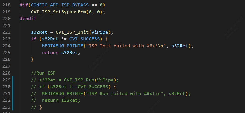
During the initial bringup of a new sensor, it is recommended to comment out AE algorithm-related callbacks to exclude the influence of the algorithm.
Modify components/cvi_platform/media/src/media_video.c by first removing the CVI_ISP_Run call.
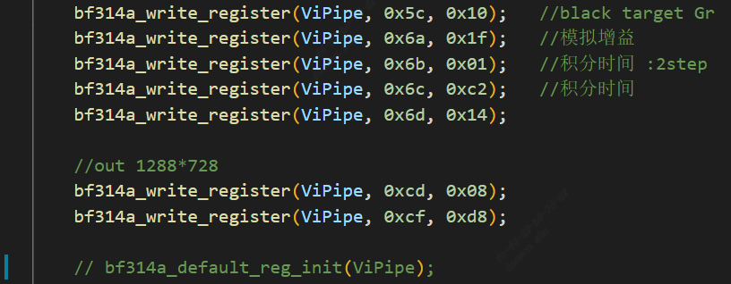
Modify the init function in xxx_cmos_ctrl.c by first annotating the call to xxx_default_reg_init.
Remember to turn these annotations back on when the sensor is ready to display the image.
5.2.1. Prepare Sensor actuation
According to the Sensor manufacturer, maximum resolution and WDR mode, select the sensor driver with the closest specifications in the release package to modify and compile the sensor library.
Specifically, see xxxx_cmos_ex.h, xxxx_cmos_param.h and xxxx_sensor_ctl.c in mars_alios/components/cvi_mmf_sdk/cvi_sensor/xxxx
Modify the I2C configuration in xxxx_sensor_ctl.c as i2c_addr, addr_byte and data_byte
const CVI_U8 bf314a_i2c_addr = 0x6e;
const CVI_U32 bf314a_addr_byte = 1;
const CVI_U32 bf314a_data_byte = 1;
According to the sensor interface specification, modify xxxx_rx_attr and pfnGetRxAttr in xxxx_cmos_param.h to set the attribute of mipi-rx.
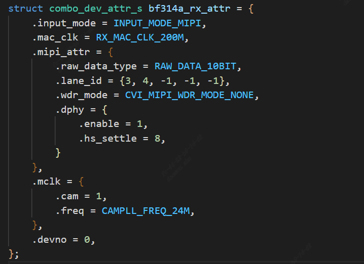
.Set whether the input mode is mipi or lvds, etc.

.Mac clk: mac clock frequency

.raw_date_type:The bit width of data

.lane id:ID configuration of mipi data lane and clock lane

.cam: mclk ID

.freq: The reference input clock provided by the SOC to the sensor

.devno:mipirx number, sensor ID
According to the sensor output mode, modify g_astxxx_mode in xxxx_cmos_param.h.
static const BF314A_MODE_S g_astBf314a_mode[BF314A_MODE_NUM] = {
   [BF314A_MODE_1280X720P30] = {
      .name = "1280X720P30",
      .astImg[0] = {
         .stSnsSize = {
            .u32Width = 1288,
            .u32Height = 728,
         },
         .stWndRect = {
            .s32X = 4,
            .s32Y = 4,
            .u32Width = 1280,
            .u32Height = 720,
         },
         .stMaxSize = {
            .u32Width = 1288,
            .u32Height = 728,
         },
      },
      .f32MaxFps = 30,
      .f32MinFps = 0.34, /* vts * 30 / 0xFFFF */
      .u32HtsDef = 1600,
      .u32VtsDef = 750,
      .stExp[0] = {
         .u16Min = 1,
         .u16Max = 750,
         .u16Def = 450,
         .u16Step = 1,
      },
      .stAgain[0] = {
         .u32Min = 1024,
         .u32Max = 16384,
         .u32Def = 1024,
         .u32Step = 1,
      },
      .stDgain[0] = {
         .u32Min = 1024,
         .u32Max = 16384,
         .u32Def = 1024,
         .u32Step = 1,
      },
   },
};
Modify pfn_cmos_set_image_mode to determine the corresponding sensor mode based on the specified width, height, and frame rate.
The output mode corresponding to the init sequence we generally get is the maximum resolution, that is, the all pixel scan mode.
However, in some cases, customers need to cut the data spit out of the sensor, and they need to adapt to the window crop mode, and they need to find the sensor manufacturer
Provide the corresponding init sequence in crop mode, or modify it according to the sensor spec.
5.2.2. Sensor initialization sequence
Implement the initial sequence pfn_cmos_sensor_init of the sensor mode in xxxx_sensor_ctrl.c.
Note for a moment the call to xxxx_default_reg_init inside xxxx_sensor_ctrl.c.
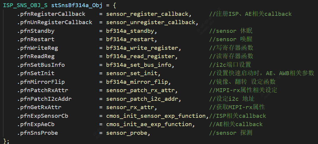
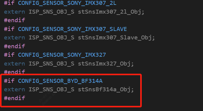
Added sensor object
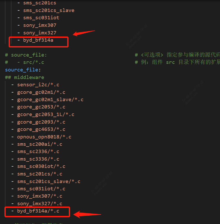
5.2.3. Modify package.yaml to add a build file
Modify components/cvi_mmf_sdk/cvi_sensor/package.yaml to add headers and source files
5.3. Adaptation solution
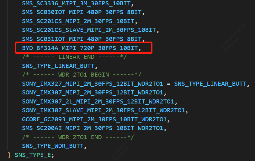
5.3.1. Add sensor type
mars_alios/components/cvi_mmf_sdk/cvi_sensor/sensor_cfg/sensor_cfg.h add a type to _SNS_TYPE_E
mars_alios/components/cvi_mmf_sdk/cvi_sensor/sensor_cfg/sensor_cfg.c
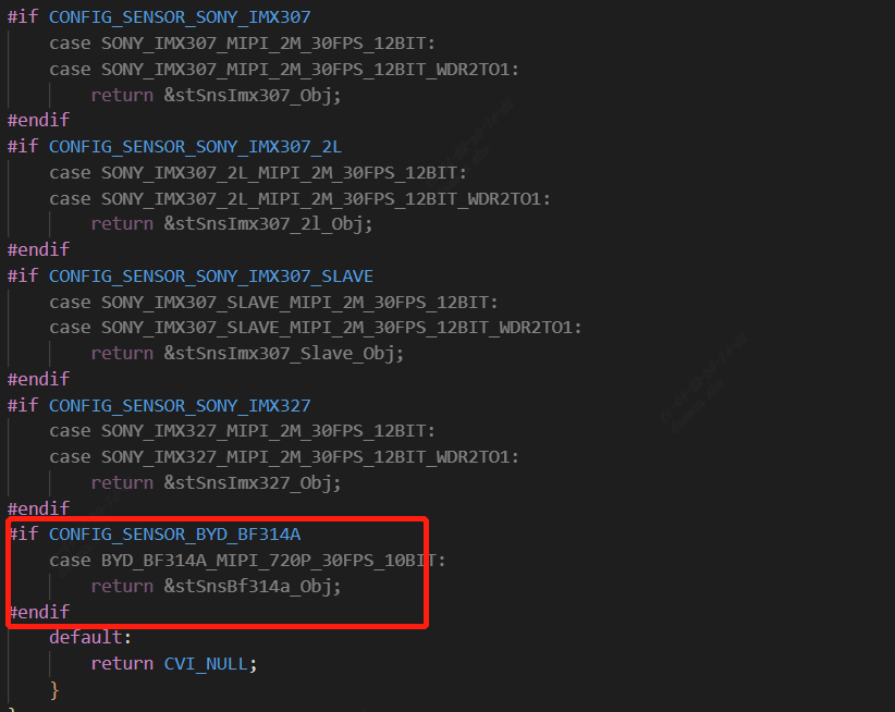
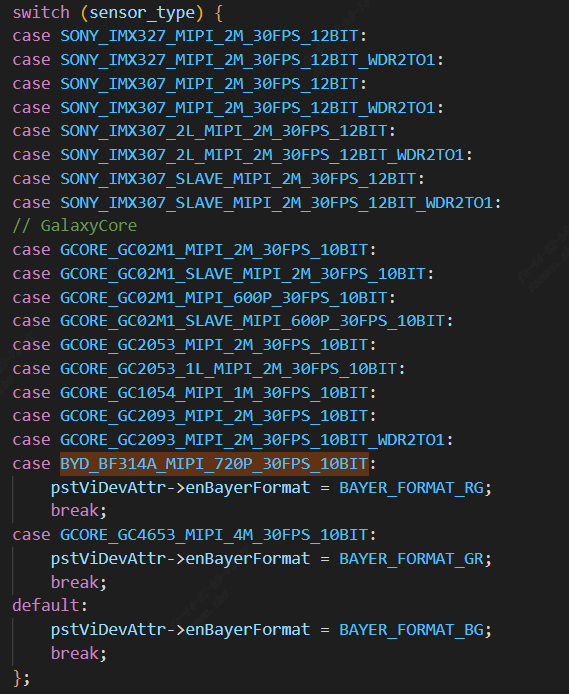
Add the sensor object, and add the corresponding case to the getPicSize and getDevAttr functions

5.3.2. Modify the sensor mipi related configuration
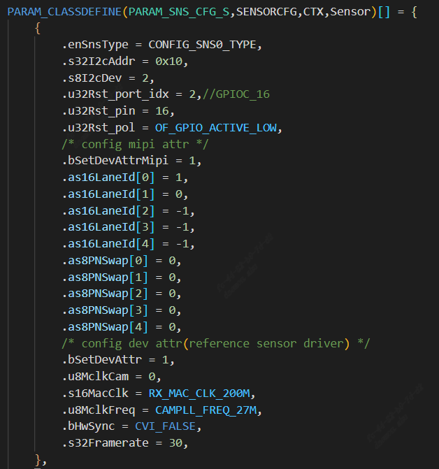
solutions/peripherals_test/customization/peripherals_qfn/param/custom_viparam.c
In this configuration, reset pin, mipi lane and other configurations will replace the information set by sensor driver by default
configuration instruction:
s32I2cAddr:sensor i2c device address
s8I2cDev:Represents the I2C port number
u32Rst_port_idx: reset the GPIO group of the pin
u32Rst_pin: reset the GPIO num of the pin
as16LaneId:Represents the linear order configuration of mipi
as8PNSwap:Denote P/N inversion, does not need to invert the configuration to 0, needs to invert the configuration to 1
u8MclkCam:Indicates which set of mclk is selected as the reference clock
s16MacClk: mac clk
u8MclkFreq: MCLK frequency
bHwSync:dual sensor frame synchronization, bHwSync =1 means slave sensor sync with master sensor
s32Framerate:frame rate
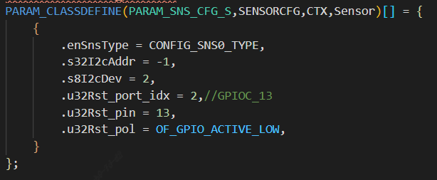
If you want to use the driver parameters by default, you can just configure the following image
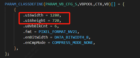
5.3.3. Modifying VB Configuration
solutions/peripherals_test/customization/peripherals_qfn/param/custom_sysparam.c Modify the u16width and u16height of VB according to the sensor output size
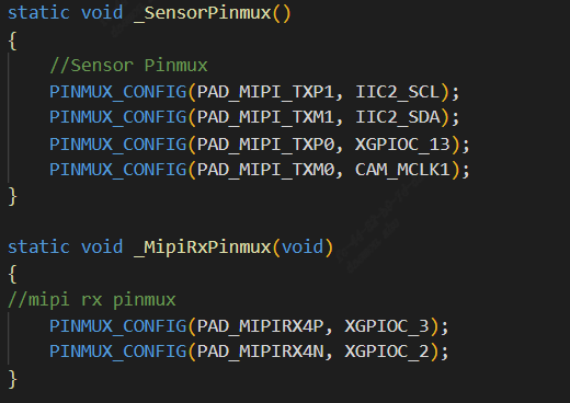
5.3.4. Modify to add pinmux
solutions/peripherals_test/customization/peripherals_qfn/src/custom_platform.c According to the actual hardware configuration of the board, modify the pin multiplexing such as mipi i2c reset
5.3.5. Modifying the build configuration
solutions/peripherals_test/package.yaml.peripherals_qfn

5.4. Running sensor
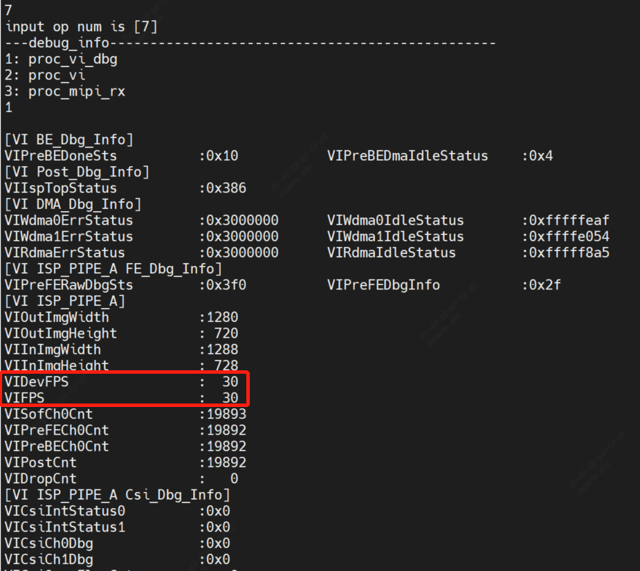
After compiling and running, the sensor will be started directly under the quick start, and the vi_dbg information will be checked by inputting proc/vi_dbg in the alios serial port. If the frame rate is normal, the sensor will produce the picture normally