4. Image Output Debugging( Linux is not a quick starter )
4.1. Hardware Preparation
Confirm that the power supply to the sensor is correct.
Confirm that the Sensor Reset GPIO is correct.
Confirm the source of the sensor’s input reference clock (main processor or external crystal oscillator).
Confirm that the I2C-writable sensor registers can be erased.
Use the default i2c_read/i2c_write commands in the file system to verify.
4.2. Configure the Initialization Sequence
Refer to the driver for the sensor of the same manufacturer in the version release package to configure the initialization sequence.
During the initial bringup of a new sensor, it is recommended to comment out AE algorithm-related callbacks to exclude the influence of the algorithm.
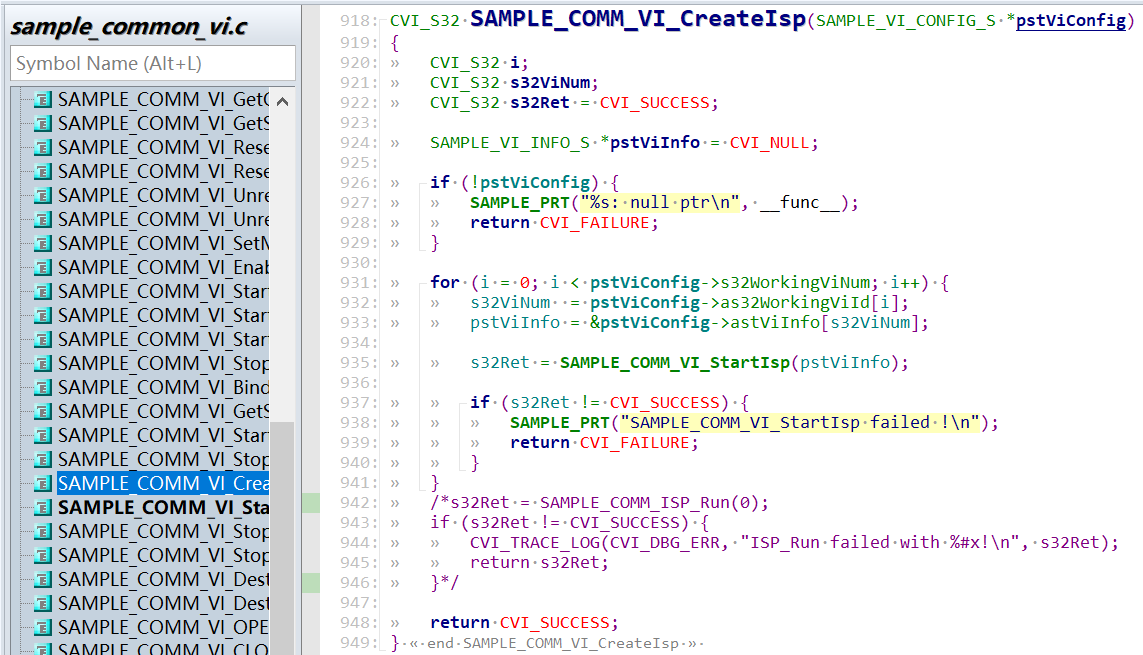
Modify sample_common_vi.c and remove the call to SAMPLE_COMM_ISP_Run.
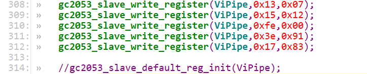
Modify the init function in xxx_cmos_ctrl.c and comment out the call to xxx_default_reg_init.
Once the sensor adaptation is complete and the image can be displayed, remember to uncomment these lines of code.
4.2.1. Prepare the sensor driver
Select the sensor driver closest to the specifications in the release package based on the sensor vendor, maximum resolution, and WDR mode, make the necessary modifications, and compile the sensor library. Details can be found in the xxxx_cmos.c, xxxx_cmos_ex.h, xxxx_cmos_param.h, and xxxx_sensor_ctl.c files in component/isp/user/sensor/cv18xx/xxxx.
Modify the I2C configuration in xxxx_sensor_ctl.c, such as i2c_addr, addr_byte, and data_byte.
const CVI_U8 imx327_i2c_addr = 0x1A;
const CVI_U32 imx327_addr_byte = 2;
const CVI_U32 imx327_data_byte = 1;
According to the sensor interface specification, modify the xxxx_rx_attr and pfnGetRxAttr in xxxx_cmos_param.h to set the attributes of the MIPI-RX.
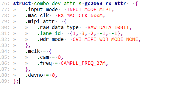
.Input_mode: Sets the input mode to MIPI, LVDS, or other interface types.
.Mac_clk: mac clock frequency.
.raw_data_type: bit width of data.
.lane id: Configuration of the MIPI data lane and clock lane IDs.
.cam: mclk ID.
.freq: Reference input clock provided by SOC to the sensor.
.devno: mipirx number, sensor ID.
According to the sensor output mode, modify g_astxxx_mode in xxxx_cmos_param.h.
static const IMX327_MODE_S g_astImx327_mode[IMX327_MODE_NUM] = {
    [IMX327_MODE_1080P30] = {
            .name = "1080p30",
            .astImg[0] = {
                    .stSnsSize = {
                            .u32Width = 1948,
                            .u32Height = 1097,
                    },
                    .stWndRect = {
                            .s32X = 12,
                            .s32Y = 8,
                            .u32Width = 1920,
                            .u32Height = 1080,
                    },
                    .stMaxSize = {
                            .u32Width = 1948,
                            .u32Height = 1097,
                    },
            },
            .f32MaxFps = 30,
            .f32MinFps = 0.119,
            .u32HtsDef = 0x1130,
            .u32VtsDef = 1125,
            .stExp[0] = {
                    .u16Min = 1,
                    .u16Max = 1123,
                    .u16Def = 400,
                    .u16Step = 1,
            },
            .stAgain[0] = {
                    .u16Min = 1024,
                    .u16Max = 62416,
                    .u16Def = 1024,
                    .u16Step = 1,
            },
            .stDgain[0] = {
                    .u16Min = 1024,
                    .u16Max = 38485,
                    .u16Def = 1024,
                    .u16Step = 1,
            },
            .u16RHS1 = 11,
            .u16BRL = 1109,
            .u16OpbSize = 10,
            .u16MarginVtop = 8,
            .u16MarginVbot = 9,
    },
}
Modify pfn_cmos_set_image_mode to determine the corresponding sensor mode based on the specified width, height, and frame rate.
The output mode corresponding to the init sequence we generally get is the maximum resolution, that is, the all pixel scan mode.
However, in some cases, customers need to cut the data spit out of the sensor, and they need to adapt to the window crop mode, and they need to find the sensor manufacturer
Provide the corresponding init sequence in crop mode, or modify it according to the sensor spec.
4.2.2. Sensor initialization sequence
Implement pfn_cmos_sensor_init, the initial sequence for the sensor mode, in xxxx_sensor_ctrl.c.
Temporarily comment out the call to xxxx_default_reg_init in xxxx_sensor_ctrl.c.
Add new sensor object.
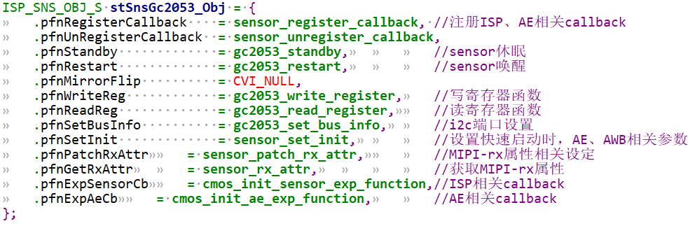
4.3. Adapting to Sample Common and alios config
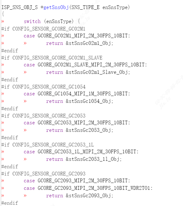
extern the sensor object to
mars_alios/components/cvi_mmf_sdk/cvi_sensor/sensor_cfg/sensor_cfg.c
getSnsObj(SNS_TYPE_E enSnsType) function.
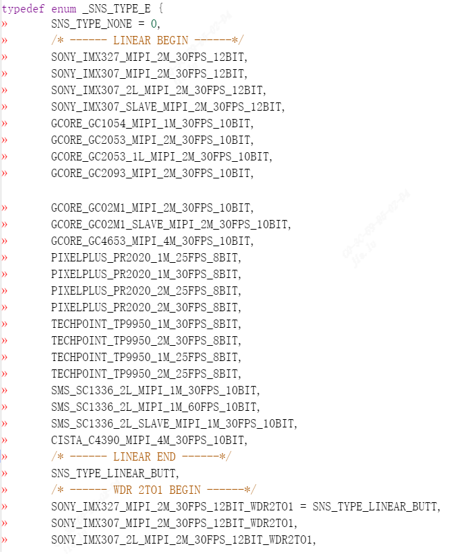
Add a new _SNS_TYPE_E to
mars_alios/components/cvi_mmf_sdk/cvi_sensor/sensor_cfg/sensor_cfg.h
In the _SNS_TYPE_E enumeration list of, linear is in the top half and WDR is in the bottom half.
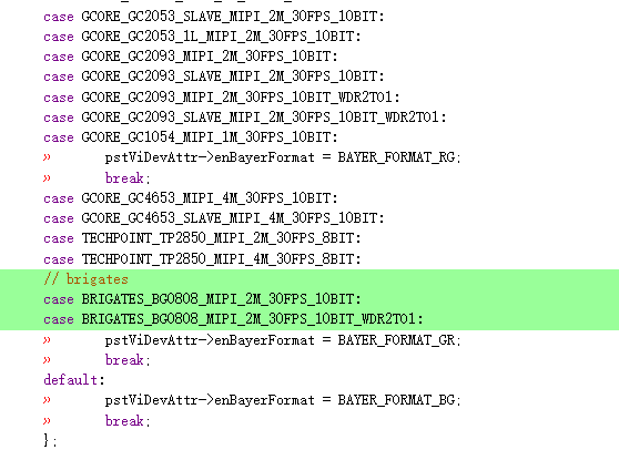
sample_common_vi.c in SAMPLE_COMM_VI_GetDevAttrBySns,
SAMPLE_COMM_VI_GetChnAttrBySns,
SAMPLE_COMM_VI_GetSizeBySensor adds the corresponding case.
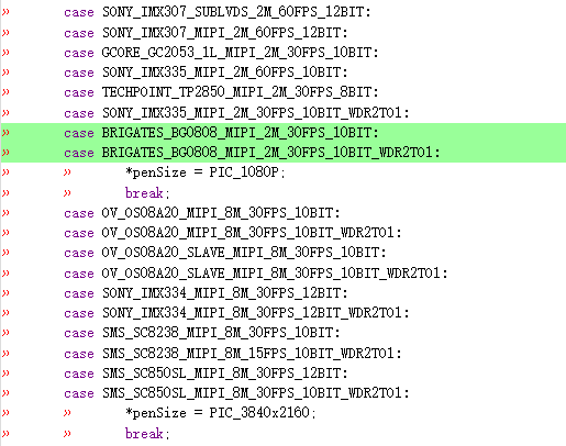
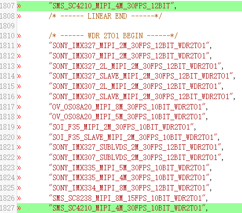
Add the new sensor name to the snsr_type_name array in sample_common_vi.c,
Notice that the sensor name is added with the new one in sensor_cfg.h
The enum of _SNS_TYPE_E has the same name and order.
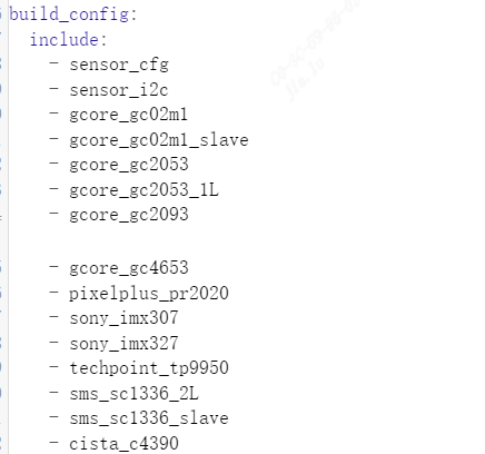
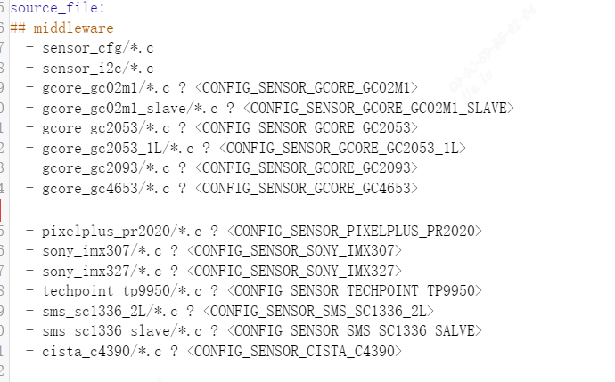
Add the sensor driver directory name and source information to mars_alios/components/cvi_mmf_sdk/cvi_sensor/package.yaml
In Linux, the sensor configuration uses the following interface, see sample for usage:
CVI_S32 CVI_SENSOR_GPIO_Init(VI_PIPE ViPipe, SNS_I2C_GPIO_INFO_S *pstGpioCfg);
To configure the reset GPIO information of each sensor, SNS_I2C_GPIO_INFO_S structure is as follows:
typedef struct _SNS_I2C_GPIO_INFO_S {
CVI_S8 s8I2cDev;
CVI_S32 s32I2cAddr;
CVI_U32 u32Rst_port_idx;
CVI_U32 u32Rst_pin;
CVI_U32 u32Rst_pol;
} SNS_I2C_GPIO_INFO_S;
CVI_S32 CVI_SENSOR_GetAhdStatus(VI_PIPE ViPipe, SNS_AHD_MODE_S *pstStatus);
Get the status of AHD Sensor, restricted to AHD sensor, SNS_AHD_MODE_S structure is as follows:
typedef enum _SNS_AHD_MODE_E {
AHD_MODE_NONE,
AHD_MODE_1280X720H_NTSC,
AHD_MODE_1280X720H_PAL,
AHD_MODE_1280X720P25,
AHD_MODE_1280X720P30,
AHD_MODE_1280X720P50,
AHD_MODE_1280X720P60,
AHD_MODE_1920X1080P25,
AHD_MODE_1920X1080P30,
AHD_MODE_2304X1296P25,
AHD_MODE_2304X1296P30,
AHD_MODE_BUIsensor_cfg.h } SNS_AHD_MODE_S;
CVI_S32 CVI_SENSOR_SetSnsType(VI_PIPE ViPipe, CVI_U32 SnsType);
Set the sensor ID of the corresponding PIPE. This method needs to be called before calling other methods. SnsType can be seen in sensor_cfg.h
CVI_S32 CVI_SENSOR_SetSnsRxAttr(VI_PIPE ViPipe, RX_INIT_ATTR_S *pstRxAttr);
To set the RX configuration of the corresponding sensor, see cvi_sns_ctrl.h for RX_INIT_ATTR_S structure
CVI_S32 CVI_SENSOR_SetSnsI2c(VI_PIPE ViPipe, CVI_S32 astI2cDev, CVI_S32 s32I2cAddr);
Set the I2C bus and address of the corresponding sensor
CVI_S32 CVI_SENSOR_SetSnsIspAttr(VI_PIPE ViPipe, ISP_INIT_ATTR_S *pstInitAttr);
To set the configuration of sensor to ISP, the ISP_INIT_ATTR_S structure is shown in cvi_sns_ctrl.h
CVI_S32 CVI_SENSOR_RegCallback(VI_PIPE ViPipe, ISP_DEV IspDev);
Set the sensor and ISP callbacks
CVI_S32 CVI_SENSOR_UnRegCallback(VI_PIPE ViPipe, ISP_DEV IspDev);
Remove the callback from the sensor and ISP
CVI_S32 CVI_SENSOR_SetSnsImgMode(VI_PIPE ViPipe, ISP_CMOS_SENSOR_IMAGE_MODE_S *stSnsrMode);
Set the mode of the sensor to run, including fps, size, etc., ISP_CMOS_SENSOR_IMAGE_MODE_S structure see cvi_comm_sns.h
CVI_S32 CVI_SENSOR_SetSnsWdrMode(VI_PIPE ViPipe, WDR_MODE_E wdrMode);
Set the sensor WDR mode; see cvi_comm_cif.h for the WDR_MODE_E structure
CVI_S32 CVI_SENSOR_GetSnsRxAttr(VI_PIPE ViPipe, SNS_COMBO_DEV_ATTR_S *stDevAttr);
Get the RX configuration of the sensor, SNS_COMBO_DEV_ATTR_S structure in cvi_comm_cif.h
CVI_S32 CVI_SENSOR_SetSnsProbe(VI_PIPE ViPipe);
Set the probe of the sensor corresponding to the PIPE
CVI_S32 CVI_SENSOR_SetSnsGpioInit(CVI_U32 devNo, CVI_U32 u32Rst_port_idx, CVI_U32 u32Rst_pin, CVI_U32 u32Rst_pol);
Configure the reset GPIO information of each sensor, u32Rst_port_idx, u32Rst_pin, u32Rst_pol, see the ini configuration content in the next section
CVI_S32 CVI_SENSOR_RstSnsGpio(CVI_U32 devNo, CVI_U32 rstEnable);
Pull the rst foot of the sensor to the valid position
CVI_S32 CVI_SENSOR_RstMipi(CVI_U32 devNo, CVI_U32 rstEnable);
reset the MIPI used by the corresponding sensor
CVI_S32 CVI_SENSOR_SetMipiAttr(VI_PIPE ViPipe, CVI_U32 SnsType);
The RX of the sensor is configured to the CIF
CVI_S32 CVI_SENSOR_EnableSnsClk(CVI_U32 devNo, CVI_U32 clkEnable);
enable sensor mclk
CVI_S32 CVI_SENSOR_SetSnsStandby(VI_PIPE ViPipe);
Set the standby state of the sensor
CVI_S32 CVI_SENSOR_SetSnsInit(VI_PIPE ViPipe);
Set the sensor start init
CVI_S32 CVI_SENSOR_SetVIFlipMirrorCB(VI_PIPE ViPipe, VI_DEV ViDev);
Register the mirror and flip of the sensor into VI
The following methods are provided to ISPs for use. Please check with the relevant documentation of your ISP
CVI_S32 CVI_SENSOR_GetAeDefault(VI_PIPE ViPipe, AE_SENSOR_DEFAULT_S *stAeDefault);
The AE default status of the corresponding sensor is obtained
CVI_S32 CVI_SENSOR_GetIspBlkLev(VI_PIPE ViPipe, ISP_CMOS_BLACK_LEVEL_S *stBlc);
To obtain the BLK value of the corresponding sensor, the ISP_CMOS_BLACK_LEVEL_S structure is given in cvi_comm_sns.h
CVI_S32 CVI_SENSOR_SetSnsFps(VI_PIPE ViPipe, CVI_U8 fps, AE_SENSOR_DEFAULT_S *stSnsDft);
Set the output FPS of the sensor
CVI_S32 CVI_SENSOR_GetExpRatio(VI_PIPE ViPipe, SNS_EXP_MAX_S *stExpMax);
Get the exposure range of the sensor
CVI_S32 CVI_SENSOR_SetDgainCalc(VI_PIPE ViPipe, SNS_GAIN_S *stDgain);
Set the digital gain value of the sensor
CVI_S32 CVI_SENSOR_SetAgainCalc(VI_PIPE ViPipe, SNS_GAIN_S *stAgain);
Set the simulated gain value of the sensor
4.4. Adding Sensor INI Configuration
Some properties of Sensor can be modified by changing ini configuration, such as lane line order, I2C port sensor output mode, etc.
By default, the middleware process will first read the sensor configuration file from /mnt/data/sensor_ini.cfg. If there is no configuration file in that directory, it will use the initial value from the code.
The following shows the contents of sensor_cfg.ini using SC1336 as an example:
[source]

;type = SOURCE_USER_FE

dev_num = 1

; section for sensor

[sensor]

; sensor name

name = SMS_SC1336_2L_MIPI_1M_60FPS_10BIT

bus_id = 3

mipi_dev = 0

lane_id = 2, 3, 1, -1, -1

pn_swap = 1, 1, 1, 0, 0

mclk_en = 1

mclk = 0

port = 0

pin = 2

pol = 1

fps = 60
name: This indicates the output mode of the sensor; be sure to match the name of the SAMPLE_SNS_TYPE_E enum added to sample_comm.h.
Bus_id: This indicates the I2C port number
Mipi_dev: This indicates which set of mipi-rx is used
Lane_id: This indicates the linear order configuration of mipi
pn_swap: Indicates whether this set of mipi linear order P/N needs to be reversed
Pn_swap: denotes P/N inversion, does not need to be reversed to 0 configuration, needs to be reversed to 1 configuration
Mclk: This specifies which set of MCLKS is selected as the reference clock
Mclk_en: This indicates which set of mclk outputs is enabled
hw_sync: dual sensor frame synchronization, hw_sync=1 means slave sensor sync with master sensor
sns_i2c_addr: The i2c device address of the sensor
port: The sensor RST pin corresponds to port A/B/ C-0/1/2 used by the GPIO of the processor
pin: The sensor RST pin corresponds to the number of the port used by the GPIO of the processor
pol: The effective level of the sensor RST pin
- The corresponding parameters are configured as follows:
enum of_gpio_flags {
OF_GPIO_ACTIVE_LOW = 0x1,
OF_GPIO_SINGLE_ENDED = 0x2,
OF_GPIO_OPEN_DRAIN = 0x4,
OF_GPIO_TRANSITORY = 0x8,
OF_GPIO_PULL_UP = 0x10,
OF_GPIO_PULL_DOWN = 0x20,
};
fps:The output fps of sensor is set to 25 by default, and other fps need to set the corresponding fps value
4.5. Build and run sensor test
After the configuration in the previous section, run make peripherals_test in the top-level SDK directory to compile, and burn the compiled firmware to the board side;
After the burn boot, the Linux serial terminal executes sensor_test
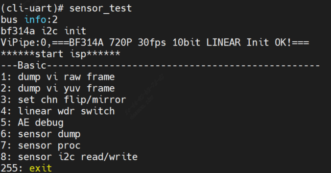
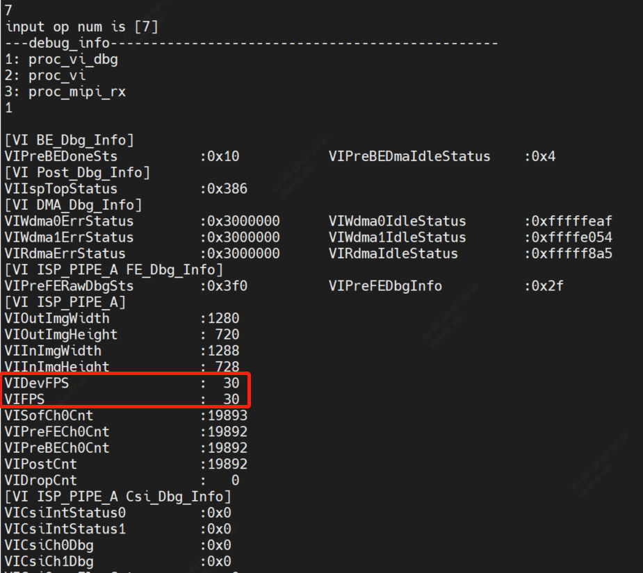
Input proc/vi_dbg in alios serial port to check vi_dbg information. If the frame rate shows normal, it means that the sensor has normal output