7. Basic Functions of ISP
The functionality of the sensor driver is implemented by operation callbacks. This chapter describes the basic functions that should be implemented by the ISP callbacks, assuming that the user is familiar with the Sensor datasheet. When debugging the ISP-related callbacks, please reopen the SAMPLE_COMM_ISP_Run and xxx_default_reg_init calls that were previously commented out.
7.1. Development Process
Please implement the following basic ISP callbacks in order:
pfn_cmos_sensor_init
pfn_cmos_sensor_exit
pfn_cmos_sensor_global_init
pfn_cmos_set_image_mode
pfn_cmos_set_wdr_mode
pfn_cmos_get_isp_default
pfn_cmos_get_sns_reg_info
7.2. Notes
pfn_cmos_sensor_init - Implement the vendor-provided initialization sequence using the sensor communication interface (I2C/SPI). The correctness of the communication interface structure should be noted. Because AE-related callbacks will also be called before the sensor initialization, the sensor AE buffer should be set before the sensor starts outputting data. Refer to the xxxx_default_reg_init in the xxxx_sensor_ctrl.c.
pfn_cmos_sensor_exit - Close the communication interface used.
pfn_cmos_sensor_global_init - Initialize the sensor driver parameters.
pfn_cmos_set_image_mode - Set the output format of the sensor. The sensor driver should choose the closest resolution as the output format.
pfn_cmos_set_wdr_mode - Set whether the sensor output is in WDR mode
pfn_cmos_get_isp_default - Provide ISP parameters related to the sensor.
pfn_cmos_get_sns_reg_info - Provide AE synchronization information stored in the sensor driver. To synchronize the AE settings with the sensor output image, when the AE callbacks are called, the sensor driver does not immediately write to the sensor buffer, but stores the modified settings. The firmware will call pfn_cmos_get_sns_reg_info at a fixed period to obtain synchronization information and pass it to the kernel space ISP driver. The ISP driver is responsible for synchronously writing to the sensor buffer. In addition, the sensor may have different WDR output formats, so the size of the image, crop position, and MIPI-RX settings may be recalculated and set with different exposure values. The sensor driver should ask the vendor for the calculation formula, and the ISP driver will update the corresponding module accordingly.
The structure returned by pfn_cmos_get_sns_reg_info is divided into three categories:
typedef struct _ISP_SNS_SYNC_INFO_S {
  ISP_SNS_REGS_INFO_S snsCfg;
  ISP_SNS_ISP_INFO_S ispCfg;
  ISP_SNS_CIF_INFO_S cifCfg;
} ISP_SNS_SYNC_INFO_S;
snsCfg represents the sensor buffers that need to be synchronized, ispCfg represents the Crop information that needs to be synchronized, and cifCfg represents the mipi-rx settings that need to be synchronized. When need_update is True, it means that the synchronization data of this type needs to be updated by ISP at the specified u8DelayFrmNum. Each buffer in snsCfg also has bUpdate to indicate whether the buffer needs to be updated.
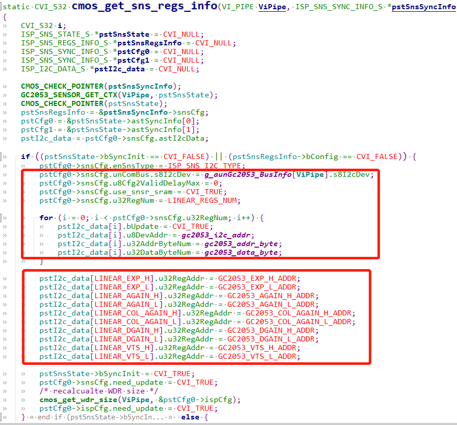
The first call to pfn_cmos_get_sns_reg_info will configure the I2C-related messages, establish register address mapping, and obtain information such as sns, crop, and WDR size, as shown in the following figure.
Subsequent calls to pfn_cmos_get_sns_reg_info are used to temporarily store modified AE register information, as shown in the following diagram.
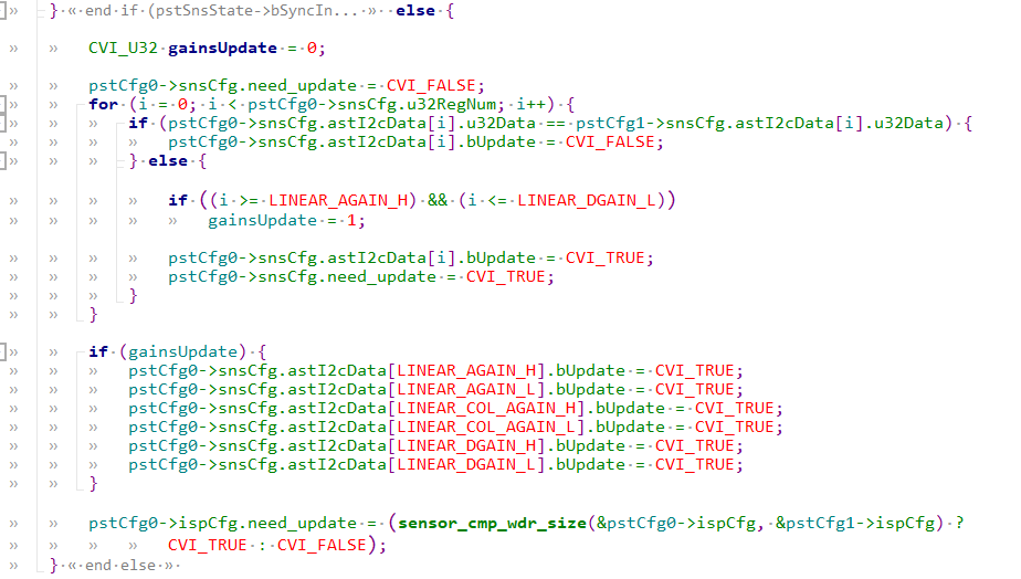
The temporarily stored AE register information will eventually be updated to the ISP driver by calling isp_snsSync_info_set, and the ISP driver will set the sensor register by sending an I2C command after delayFrmNum.
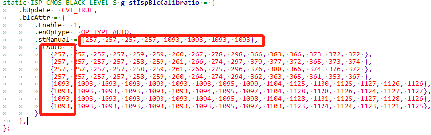
pfn_cmos_get_isp_black_level - Retrieve the black level offset from the sensor spec. Convert the offset to a 12-bit value and use it in the formula to obtain the gain: gain = 4095 / (4095 - offset) * 1024.