11. Common Problem
11.1. Proc Message Interpretation
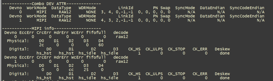
# cat /proc/mipi-rx
Combo DEV ATTR mainly provides interface configuration information for the sensor:
Devno: indicates the sensor number. 0 indicates sensor0, and 1 indicates sensor1. Currently, only two sensors can be entered at the same time.
WorkMode: indicates the interface type (mipi/sublvds/ HISPI /BT656…).
DateType: indicates the sensor data format (raw8/raw10/raw12/ YUV422_8BIT…).
WDRMode: wdr mode (none indicates non-wDR, common wdr mode:VC, DT, Manual).
LinkId: lane sequence configuration.
PN swap: indicates PN reversal. If there is PN reversal, set the lane to 1.
SyncMode/DataEndian/SyncCodeEnddian: for mipi interface does not support so no configuration, for sublvds, hispi requires configuration.
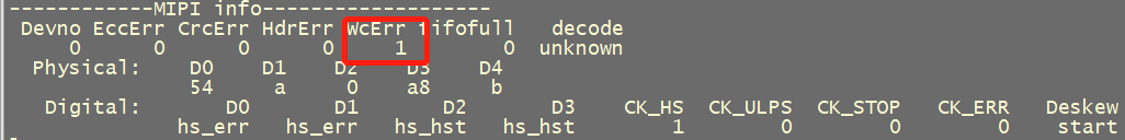
MIPI INFO mainly refers to the information parsed by mipi-rx:
EccErr, CrcErr, HdrErr, WcErr: If the value is not 0, it indicates that Ecc,crc, and wc have been used to check err. Check the correctness of lane mapping, mipi timing, and lane hardware circuit.
Fifofull: If the value is not 0, the mac speed is too slow and the mac clk needs to be increased.
Decode: parsing the data type l (Raw12 / raw10 / raw8 / YUV422…).
PhySical: D0-D4 Indicates the data on the lane bus. After the hi speed state is entered, data changes in D0-D4.
Digital: D0-D4 Displays the status of each data lane after the hi speed state is entered. CK_HS, CK_ULPS, CK_ERR, and Deskew indicate the status of clk lane. Normally, CK_HS=1 and the rest value is 0, but CK_HS=1 and CK_STOP=1 continue.
11.3. How to Configure Lane Line Sequence
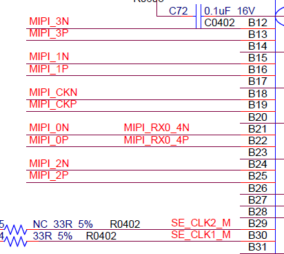
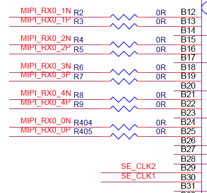
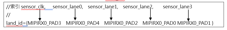
Note that the lane id to be configured should be configured with the sensor as the reference. The index number of lane_id array represents the Lane ID of the Sensor, the index number 0 represents the sensor clock, and the index number 1-4 represents sensor lane 0~3. The value of the land_id array indicates the Lane ID of MIPI-Rx of soc. 0 indicates MIPIRX1_PAD0 and 1 indicates MIPIRX1_PAD1. lane_id is set to -1 for unused lanes.
Assume that the lane connection of sensor and soc is shown in the figure below, and the corresponding lane id configuration is {3,4,2,0,1}.
sensor:
soc:
SENSOR Pins |
MIPI Lane Pins |
|---|---|
MIPI_CK (index = 0) |
MIPIRX0_3 (value = 0) |
MIPI_0 (index = 1) |
MIPIRX0_4 (value = 1) |
MIPI_1 (index = 2) |
MIPIRX0_2 (value = 2) |
MIPI_2 (index = 3) |
MIPIRX0_0 (value = 3) |
MIPI_3 (index = 4) |
MIPIRX0_1 (value = 4) |
11.4. How to Select the MAC Frequency
MAC represents how often the isp receives data from the sensor,
Formula MAC_Freq * pix_width = lane_num * MIPI_Freq * 2.
MAC_Freq: VI MAC operating frequency.
pixel_width: pixel bit width.
lane_num: indicates the number of MIPI lanes.
MIPI_Freq: operating frequency of each lane.
Assuming that the MAC freq is 400 M, pixel_width = 12, lane_num = 4, the maximum MIPI_Freq = 400 * 12 / (4 * 2) = 600MHz is supported.
Where MIPI_Freq means phy_Clk, the value is bps/2. For example, the specifications of sony imx335 are 1188Mbps per lane and phy_clk = 1188/2=594Mhz.
Conversely, if the sensor gives us the data rate, we need to be able to figure out the appropriate mac freq.
11.5. Error Checking Process

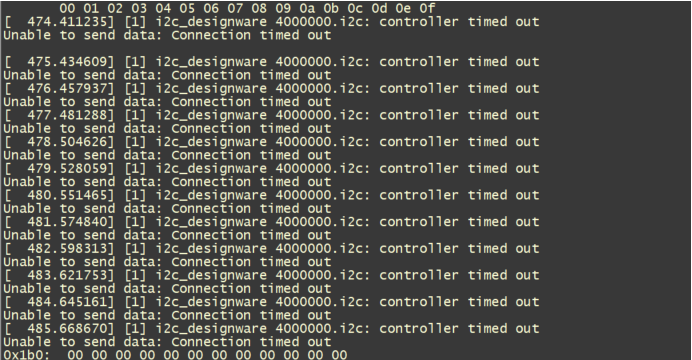
I2C Write Fail
Sensor i2c attribute confirmation.
Check the I2C bus id.
Check the I2C slave addr.
Check the addr/data bit width of the sensor register (8bit or 16bit).
If the bit width is incorrectly configured, a time out error is displayed.
Check whether the hardware is normal.
Verify that the rst, pwdn, and mclk pins in the dts are correctly configured.
echo “snsr_on 0 1 1” > /proc/mipi-rx //1 indicates 37.125M, 2 indicates 25M, and 3 indicates 27M
echo “snsr_on 1 1 1” > /proc/mipi-rx // 1 indicates 37.125M, 2 indicates 25M, and 3 indicates 27M
echo “snsr_r 0 0” > /proc/mipi-rx
echo “snsr_r 1 0” > /proc/mipi-rx
Run the i2cdetect -y -r N command to test whether the i2c can detect the detection. N Indicates the i2c port corresponding to the sensor.
Check if the power on timing meets spec requirements (measure MCLK and I2C with an oscilloscope).
Decode err
cat /proc/mipi-rx, check the proc message and check whether the Proc message is in hs-state. After the sensor is powered, it will enter the high speed state from the low power state. As shown in the following figure, if D0-D4 of mipi-rx has data and keeps changing, it indicates that hs-state is entered.

Confirm i2c pathways (i2cdetect can sweep out sensor address).
Confirm order right lane line.
If the data lane in proc has no data jump and the accompanying CK_HS is 0, the clk lane is not found correctly (please confirm the clk lane).
If there is data jump in the data lane in proc and CK_HS is 1, it means that the clk lane is found correctly and has entered hs mode. If ecc, crc and other errors occur, it means that the data lane is not configured correctly (please confirm the data lane).
Confirm timing.
If the previous two points are confirmed to be correct, but CK_HS =0 and there is no data jump in the data lane, the timing may not meet the conditions for entering hs. In this case, the value of hs-zero and hs-trail can be adjusted and increased to lengthen the detect period.
If the first two points are confirmed to be correct, CK_HS =1, data lane has data jump, but there are still ecc, crc and other err, it may be that the setting of Hs-settle is too large or too small, and the data behind is pressed.
Confirm whether the hw is damaged.
ECC err
Check lane Id mapping.
Check sensor tx hs-zero/hs-prepare.
hs-zero and hs-parepare need to determine the value from sensor spec or directly ask the sensor manufacturer. It is not recommended to adjust the value.
Check mipi-rx hs-settle.
When the hs-settle time is too long, the “sync code” in the data will be pressed, and the “sync code” cannot be resolved, resulting in ecc err.
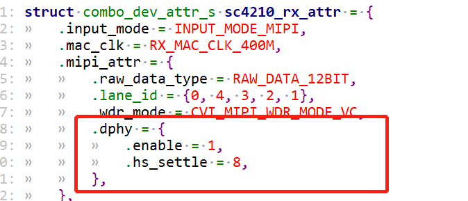
Adjust hs-settle you can directly modify xxx_cmos_param.h as follows, fill in the correct hs_settle.
You can also directly ctrl+z to adjust hs-settle, and use devmem command to modify the bit[23:16] value of register 0x0300b048. After adjustment, enter fg to jump back to the program.
devmem 0x0300b048 32 0xXYZ

CRC err/Word count err
Adjust the sensor tx hs-trail. If the hs-trail is pulled too fast, the data behind it may be pressed, resulting in data loss, resulting in crc err and wc err. You need to adjust the hs-trail register setting of the sensor.
vi_select timeout
cat/proc/mipi - rx show whether there is the i2c, decode, ecc, CRC, wc etc. err. If the preceding 4 steps are correct, cat /proc/cvitek-vi_dbg checks for WidthGTCnt, WidthLSCnt, HeightGTCnt, and HeightLSCnt. If such error occurs, crop size in sensor init setting is inconsistent with the set given to isp. Please confirm the modification against sensor spec.
Check whether MAC clock is too low, if the MAC clock is too low, can lead to an isp processing speed too slow in fifo full, can also lead to the timeout.