9. Complete Other Functions
9.1. Sensor Initialization Process
In addition to AE/ISP, the sensor driver also uses other callbacks to complete the initialization process. Some parameter settings in sensor callbacks may affect each other, so the order of calling needs to be carefully considered. The recommended call sequence is as follows:

During the pre-init phase, the environment for the Sensor driver is prepared and the following callbacks are called:
pfnSetInit - Initializes common parameters for the sensor. The enGainMode determines the behavior of the sensor’s gain in WDR mode.
pfnSetBusInfo - Sets I2C information.
pfnRegisterCallback - Registers the sensor ISP/AE callbacks.
pfn_cmos_sensor_global_init - Initializes internal parameters of the sensor driver.
Set Mode determines the main output format of the sensor, and the following callbacks are called:
pfn_cmos_set_image_mode - Sets the output image format.
pfn_cmos_set_wdr_mode - Sets the linear or WDR mode.
Set User Default is used to set the AE parameters for the initialization sequence, and the following callbacks are called:
pfn_cmos_fps_set - Sets the frame rate per second. The default frame rate f32Fps is obtained from the callback pfn_cmos_get_ae_default, and the new frame rate must not be greater than the default value.
pfn_cmos_inttime_update - Sets the number of exposure lines and returns it to AE. In linear mode, the exposure line count range can be obtained from u32MaxIntTime and u32MinIntTime in pfn_cmos_get_ae_default. In WDR mode, pfn_cmos_get_inttime_max can be called to obtain the exposure line count range for long and short exposures based on the exposure ratio.
pfn_cmos_gains_update - Sets the Sensor’s AGAIN and DGAIN. The Gain range can be obtained from u32MaxAgain/u32MaxDgain and u32MinAgain/u32MinDgain in pfn_cmos_get_ae_default, and the closest Gain and corresponding Sensor buffer settings can be obtained from pfn_cmos_again_calc_table/pfn_cmos_dgain_calc_table.
Init Mipi-Rx initializes Mipi-Rx parameters and the Sensor’s Power On Sequence by calling the Mipi-Rx driver in the kernel via ioctl. The main program steps are as follows:
Open /dev/video0, which opens VIP-related power and clock sources.
Call the callback pfnGetRxAttr in the Sensor driver to obtain the corresponding Mipi-Rx settings.
CVI_MIPI_RESET_SENSOR - ioctl for Mipi-Rx, calling it opens the Sensor Reset pin defined in the device tree.
  mipi_rx: cif {
        compatible = "cvitek,cif";
        reg = <0x0 0x0a0c2000 0x0 0x2000>, <0x0 0x0300b000 0x0 0x1000>,
                <0x0 0x0a0c4000 0x0 0x2000>, <0x0 0x0300d000 0x0 0x1000>;
        reg-names = "csi_mac0", "csi_wrap0", "csi_mac1", "csi_wrap1";
        interrupts = <GIC_SPI 155 IRQ_TYPE_LEVEL_HIGH>, <GIC_SPI 156 IRQ_TYPE_LEVEL_HIGH>;
        interrupt-names = "csi0", "csi1";
        snsr-reset = <&portd 7 GPIO_ACTIVE_LOW>, <&portd 7 GPIO_ACTIVE_LOW>;
        resets = <&rst RST_CSIPHY0>, <&rst RST_CSIPHY1>,
                <&rst RST_CSIPHY0RST_APB>, <&rst RST_CSIPHY1RST_APB>;
        reset-names = "phy0", "phy1", "phy-apb0", "phy-apb1";
};
CVI_MIPI_RESET_MIPI - ioctl for Mipi-Rx, calling it resets the Mipi-Rx settings.
CVI_MIPI_SET_DEV_ATTR - ioctl for Mipi-Rx, calling it sets the Mipi-Rx properties.
CVI_MIPI_ENABLE_SENSOR_CLOCK - ioctl for Mipi-Rx, calling it turns on the Sensor clock. The frequency is determined by the mclk attribute in CVI_MIPI_SET_DEV_ATTR.
CVI_MIPI_UNRESET_SENSOR - ioctl for Mipi-Rx, calling it closes the Sensor Reset pin defined in the device tree.
To initiate the Sensor’s initial sequence, the Sensor Init calls the callback pfn_cmos_sensor_init in the Sensor driver.
9.2. Sensor Shutdown Process
When closing the sensor, the following process can be referred to:

Disable ISP - Disable the near-end ISP interface.
Disable Sensor - Call the sensor driver’s callback pfn_cmos_sensor_exit to close the sensor stream and I2C interface. Call pfnUnRegisterCallback to remove the sensor driver.
Call Mipi-Rx ioctl CVI_MIPI_RESET_SENSOR to activate the Sensor reset pin. Call CVI_MIPI_DISABLE_SENSOR_CLOCK to turn off the Sensor clock. Call CVI_MIPI_RESET_MIPI to reset the Mipi-Rx settings.
9.3. Sensor AE Synchronization Process
Exposure and gain settings on the sensor may be reflected in different frames, so there needs to be a mechanism to synchronize the settings between the sensor and the ISP. In addition, in WDR Manual mode, adjusting the exposure of short-exposure frames may require updating the Mipi-Rx settings. The following is the Sensor AE synchronization process:
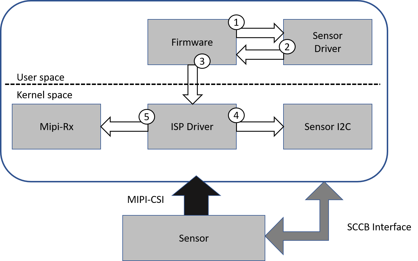
The firmware calls the sensor callbacks pfn_cmos_gains_update and pfn_cmos_inttime_update to update the AE settings.
The firmware calls the sensor callback pfn_cmos_get_sns_reg_info at fixed intervals to obtain the sensor/ISP/Mipi-Rx settings.
The firmware passes the sensor/ISP/CIF settings to the ISP driver’s synchronization processing mechanism via the ISP ioctl.
When it is necessary to update the sensor settings, the ISP driver calls the I2C interface in cv18xx_vip.ko to update the sensor cache.
When it is necessary to update the Mipi-Rx settings, the ISP driver calls the Mipi-Rx driver in cvi_mipi_rx.ko.